How to Use RoboClaw 2x15A Motor Controller: Examples, Pinouts, and Specs
Introduction
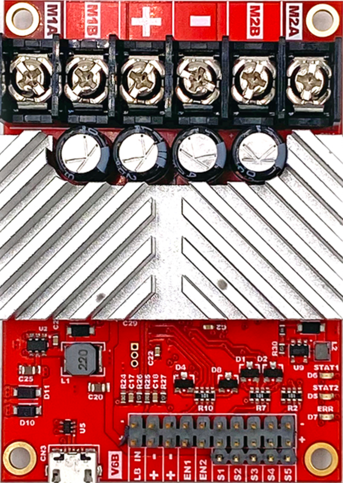
The RoboClaw 2x15A Motor Controller, manufactured by BASICMICRO (Part ID: IMC412), is a dual-channel motor controller designed to drive two DC motors with a maximum continuous current of 15A per channel. It offers advanced control features, including speed and direction control, and supports multiple communication protocols such as USB, TTL serial, RC, and analog inputs. This versatile motor controller is ideal for robotics, automation systems, and other applications requiring precise motor control.
Explore Projects Built with RoboClaw 2x15A Motor Controller

Explore Projects Built with RoboClaw 2x15A Motor Controller
Common Applications and Use Cases
- Robotics: Controlling drive motors for mobile robots.
- Automation: Operating conveyor belts or other motorized systems.
- Remote-Controlled Vehicles: Managing speed and direction of RC cars, boats, or drones.
- Industrial Systems: Driving motors in automated machinery or equipment.
Technical Specifications
Key Technical Details
- Input Voltage Range: 6V to 34V DC
- Continuous Current: 15A per channel
- Peak Current: 30A per channel (for short durations)
- Communication Protocols: USB, TTL Serial, RC, Analog
- Encoder Support: Quadrature encoders for closed-loop control
- PWM Frequency: 20kHz
- Dimensions: 2.75" x 2.00" x 0.75" (70mm x 50mm x 19mm)
- Weight: 2.5 oz (70g)
Pin Configuration and Descriptions
The RoboClaw 2x15A Motor Controller features multiple connectors for power, motor outputs, and communication. Below is a detailed description of the pin configuration:
Power and Motor Connections
| Pin Name | Description |
|---|---|
| VIN+ | Positive input voltage (6V to 34V DC). |
| VIN- | Ground connection for input voltage. |
| M1A, M1B | Motor 1 output terminals. |
| M2A, M2B | Motor 2 output terminals. |
Communication and Control Connections
| Pin Name | Description |
|---|---|
| S1, S2 | RC signal inputs for motor control. |
| A1, A2 | Analog inputs for motor control. |
| TX, RX | TTL serial communication pins. |
| USB | USB port for PC communication and configuration. |
| ENC1A, ENC1B | Encoder inputs for Motor 1. |
| ENC2A, ENC2B | Encoder inputs for Motor 2. |
Status and Feedback
| Pin Name | Description |
|---|---|
| Status LED | Indicates power and error status. |
| BEC Output | 5V regulated output for powering external devices. |
Usage Instructions
How to Use the Component in a Circuit
- Power Connection: Connect a DC power supply (6V to 34V) to the VIN+ and VIN- terminals. Ensure the power supply can handle the current requirements of your motors.
- Motor Connection: Connect the two DC motors to the M1A/M1B and M2A/M2B terminals. Ensure proper polarity for desired motor direction.
- Control Input: Choose a control method (e.g., USB, TTL serial, RC, or analog) and connect the appropriate pins.
- Encoder Connection (Optional): If using encoders for closed-loop control, connect the encoder outputs to the ENC1A/ENC1B and ENC2A/ENC2B pins.
- Configuration: Use the BasicMicro Motion Studio software (via USB) to configure the motor controller settings, such as motor type, control mode, and PID parameters.
Important Considerations and Best Practices
- Heat Dissipation: Ensure adequate ventilation or use a heatsink if operating at high currents for extended periods.
- Power Supply: Use a power supply with sufficient current capacity to avoid voltage drops or damage to the controller.
- Wiring: Use appropriately rated wires for power and motor connections to handle the current without overheating.
- Safety: Always test the system with low power before full operation to ensure proper wiring and configuration.
Example: Using RoboClaw with Arduino UNO
The RoboClaw can be controlled via TTL serial communication with an Arduino UNO. Below is an example code snippet to control motor speed and direction:
#include <SoftwareSerial.h>

// Define RoboClaw serial pins
#define ROBOCLAW_RX 10  // Arduino pin connected to RoboClaw TX
#define ROBOCLAW_TX 11  // Arduino pin connected to RoboClaw RX

// Create a SoftwareSerial object for RoboClaw communication
SoftwareSerial roboclaw(ROBOCLAW_RX, ROBOCLAW_TX);

void setup() {
  roboclaw.begin(38400); // Initialize RoboClaw serial communication at 38400 baud
}

void loop() {
  // Example: Set Motor 1 to 50% forward speed
  sendCommand(128, 0, 64); // Address 128, Command 0 (M1 Forward), Speed 64 (50%)

  delay(2000); // Run motor for 2 seconds

  // Example: Stop Motor 1
  sendCommand(128, 0, 0); // Address 128, Command 0 (M1 Forward), Speed 0

  delay(2000); // Wait for 2 seconds
}

// Function to send a command to RoboClaw
void sendCommand(uint8_t address, uint8_t command, uint8_t value) {
  roboclaw.write(address);  // Send RoboClaw address
  roboclaw.write(command);  // Send command
  roboclaw.write(value);    // Send value (speed or direction)
  uint16_t checksum = address + command + value; // Calculate checksum
  roboclaw.write(checksum & 0xFF); // Send lower byte of checksum
  roboclaw.write((checksum >> 8) & 0xFF); // Send upper byte of checksum
}
Troubleshooting and FAQs
Common Issues and Solutions
Motors Not Running:
- Verify power supply voltage and current capacity.
- Check motor connections for proper wiring.
- Ensure the control input (e.g., USB, TTL serial) is configured correctly.
Overheating:
- Reduce motor load or operating current.
- Improve ventilation or add a heatsink to the controller.
Communication Errors:
- Check baud rate and communication settings.
- Ensure proper wiring for TTL serial or USB connections.
Erratic Motor Behavior:
- Verify encoder connections and settings if using closed-loop control.
- Check for noise or interference in control signals.
FAQs
Q: Can I use the RoboClaw with a Raspberry Pi?
A: Yes, the RoboClaw supports TTL serial communication, which can be interfaced with a Raspberry Pi's UART pins.
Q: What happens if the current exceeds 15A?
A: The RoboClaw has built-in overcurrent protection. If the current exceeds 15A continuously, the controller will throttle or shut down to prevent damage.
Q: How do I update the firmware?
A: Use the BasicMicro Motion Studio software via the USB connection to update the firmware.
Q: Can I control brushless motors with the RoboClaw?
A: No, the RoboClaw is designed for brushed DC motors only.