How to Use Voltage Regulator: Examples, Pinouts, and Specs
Introduction
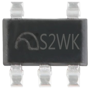
The Voltage Regulator (Manufacturer: S2WK, Part ID: ME6211CXXG / ME6211HXXG) is a compact and efficient device designed to maintain a constant output voltage level, regardless of fluctuations in input voltage or load conditions. This component is widely used in electronic circuits to ensure stable power delivery to sensitive components, preventing damage and ensuring reliable operation.
Explore Projects Built with Voltage Regulator


Explore Projects Built with Voltage Regulator
Common Applications and Use Cases
- Power supply stabilization for microcontrollers, sensors, and ICs.
- Battery-powered devices to regulate voltage as the battery discharges.
- Noise reduction in sensitive analog and digital circuits.
- Voltage regulation in portable electronics, such as smartphones and wearables.
Technical Specifications
The ME6211CXXG / ME6211HXXG voltage regulator is a low-dropout (LDO) linear regulator with high accuracy and low quiescent current. Below are the key technical details:
Key Specifications
| Parameter | Value |
|---|---|
| Input Voltage Range | 2.0V to 6.0V |
| Output Voltage Options | 1.2V to 5.0V (fixed, depending on model) |
| Output Current | Up to 500mA |
| Dropout Voltage | 200mV (typical at 300mA load) |
| Quiescent Current | 45µA (typical) |
| Output Voltage Accuracy | ±2% |
| Operating Temperature | -40°C to +85°C |
| Package Options | SOT-23-5, SOT-89-3 |
Pin Configuration and Descriptions
SOT-23-5 Package
| Pin Number | Pin Name | Description |
|---|---|---|
| 1 | VIN | Input voltage (2.0V to 6.0V) |
| 2 | GND | Ground |
| 3 | VOUT | Regulated output voltage |
| 4 | CE | Chip enable (active high) |
| 5 | NC | No connection (leave unconnected) |
SOT-89-3 Package
| Pin Number | Pin Name | Description |
|---|---|---|
| 1 | VIN | Input voltage (2.0V to 6.0V) |
| 2 | GND | Ground |
| 3 | VOUT | Regulated output voltage |
Usage Instructions
How to Use the Voltage Regulator in a Circuit
Connect the Input Voltage (VIN):
- Ensure the input voltage is within the specified range (2.0V to 6.0V).
- Use a decoupling capacitor (e.g., 1µF ceramic) close to the VIN pin to reduce noise.
Connect the Output Voltage (VOUT):
- Attach the load to the VOUT pin.
- Place a capacitor (e.g., 1µF ceramic) close to the VOUT pin to stabilize the output voltage.
Enable the Regulator (CE Pin):
- For the SOT-23-5 package, drive the CE pin high (logic level 1) to enable the regulator.
- If the CE pin is not used, connect it to VIN to keep the regulator always enabled.
Ground Connection (GND):
- Connect the GND pin to the circuit ground.
Important Considerations and Best Practices
- Capacitor Selection: Use low-ESR ceramic capacitors for both input and output to ensure stability.
- Thermal Management: Ensure adequate heat dissipation, especially when operating near the maximum output current.
- Load Conditions: Avoid sudden large changes in load current to prevent instability.
- Pin Compatibility: Verify the pin configuration for the specific package (SOT-23-5 or SOT-89-3) before connecting.
Example: Using the Voltage Regulator with Arduino UNO
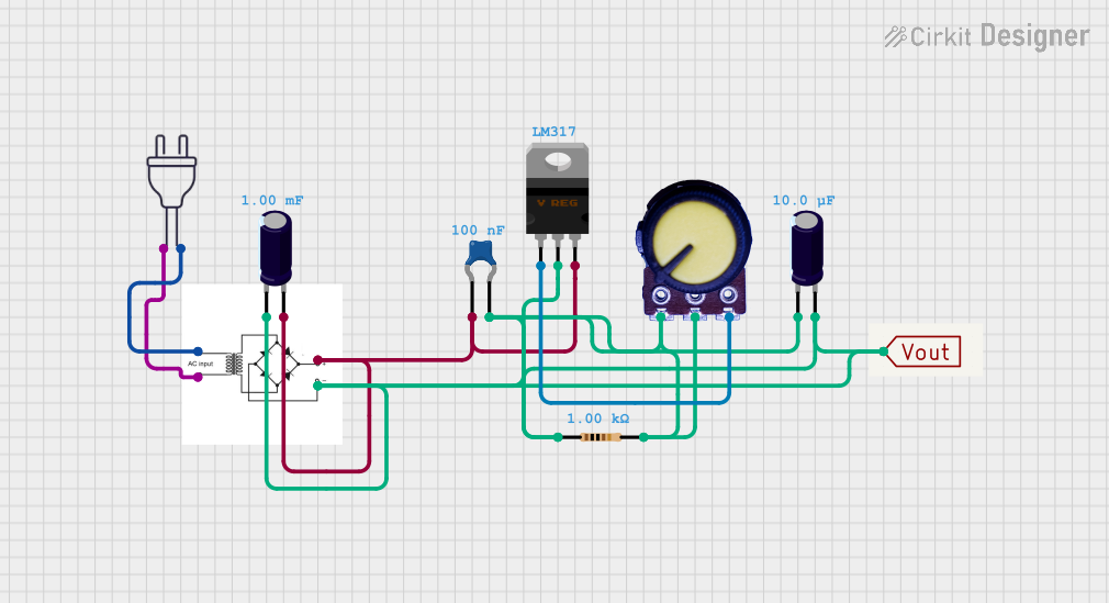
Below is an example of connecting the ME6211 voltage regulator to power an Arduino UNO with a stable 5V supply:
Circuit Diagram
- VIN: Connect to a 6V battery or power source.
- VOUT: Connect to the Arduino UNO's 5V pin.
- GND: Connect to the Arduino UNO's GND pin.
Arduino Code Example
// Example code to blink an LED using Arduino UNO powered by ME6211 regulator

const int ledPin = 13; // Pin connected to the onboard LED

void setup() {
  pinMode(ledPin, OUTPUT); // Set the LED pin as an output
}

void loop() {
  digitalWrite(ledPin, HIGH); // Turn the LED on
  delay(1000);                // Wait for 1 second
  digitalWrite(ledPin, LOW);  // Turn the LED off
  delay(1000);                // Wait for 1 second
}
Troubleshooting and FAQs
Common Issues and Solutions
No Output Voltage:
- Ensure the CE pin is connected to VIN or driven high.
- Verify the input voltage is within the specified range.
- Check for proper capacitor placement and values.
Output Voltage Instability:
- Use low-ESR ceramic capacitors for both input and output.
- Ensure the load current does not exceed the maximum rating (500mA).
- Verify proper grounding and minimize noise in the circuit.
Excessive Heat Generation:
- Check for high dropout voltage due to low input voltage.
- Reduce the load current or improve heat dissipation with a heatsink.
FAQs
Q: Can I use the ME6211 to power a 3.3V microcontroller?
A: Yes, select the appropriate model with a fixed 3.3V output voltage and ensure the input voltage is at least 3.5V (considering dropout voltage).
Q: What happens if I leave the CE pin floating?
A: The regulator may not operate correctly. Always connect the CE pin to VIN or drive it high to enable the regulator.
Q: Can I use electrolytic capacitors instead of ceramic capacitors?
A: While possible, ceramic capacitors are recommended due to their low ESR, which ensures stability and better performance.