
How to Use Solar Charge Controller: Examples, Pinouts, and Specs
 Design with Solar Charge Controller in Cirkit Designer
Introduction
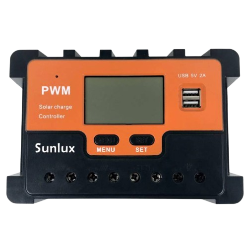
The Sunlux Orange Series PWM Solar Charge Controller is a device designed to regulate the voltage and current generated by solar panels to ensure safe and efficient charging of batteries. It prevents overcharging, over-discharging, and protects the battery from damage, thereby extending its lifespan. This controller uses Pulse Width Modulation (PWM) technology to optimize the charging process.
Explore Projects Built with Solar Charge Controller
 Open Project in Cirkit Designer
 Open Project in Cirkit Designer
 Open Project in Cirkit Designer
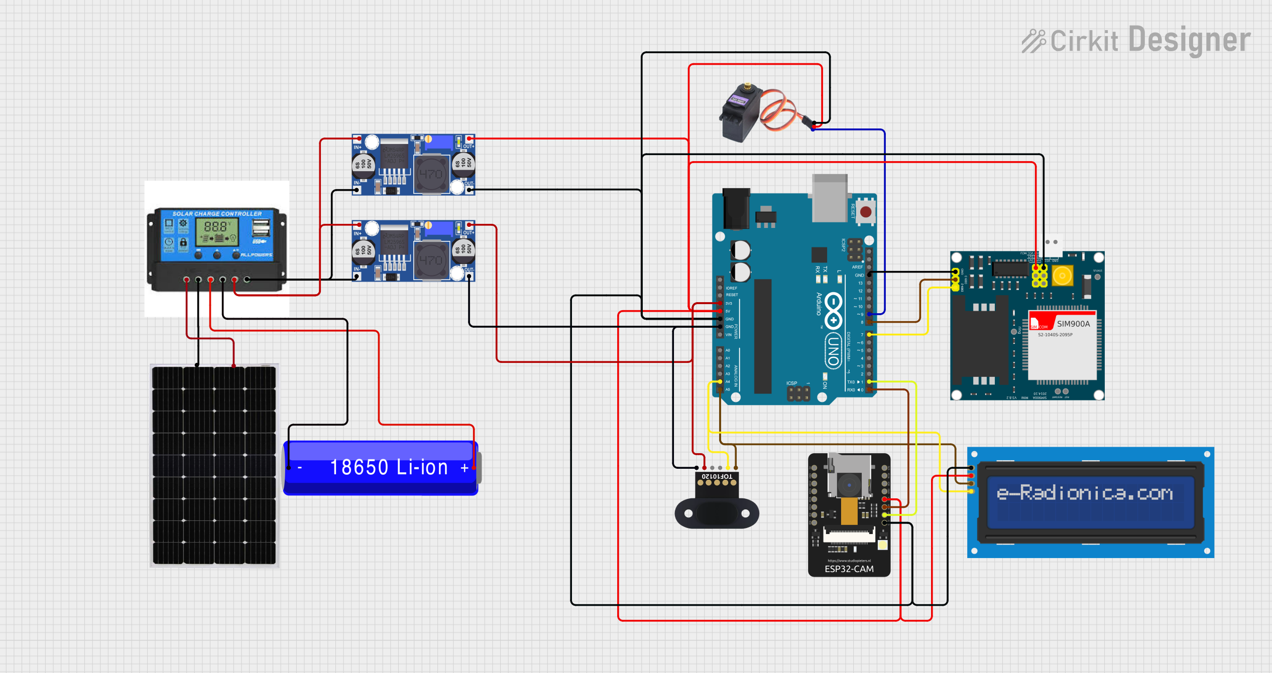 Open Project in Cirkit Designer
Explore Projects Built with Solar Charge Controller
Open Project in Cirkit DesignerOpen Project in Cirkit DesignerOpen Project in Cirkit DesignerOpen Project in Cirkit DesignerCommon Applications and Use Cases
- Off-grid solar power systems
- Solar-powered lighting systems
- RVs, boats, and caravans with solar setups
- Backup power systems with solar energy
- Small-scale renewable energy projects
Technical Specifications
The following table outlines the key technical details of the Sunlux Orange Series PWM Solar Charge Controller:
| Parameter | Value |
|---|---|
| Manufacturer | Sunlux |
| Part ID | Orange Series PWM |
| Rated Voltage | 12V / 24V Auto Recognition |
| Maximum Input Voltage | 50V |
| Rated Charge Current | 10A / 20A / 30A (model-dependent) |
| Battery Type Supported | Lead-acid, AGM, Gel |
| Charging Technology | PWM (Pulse Width Modulation) |
| Operating Temperature | -20°C to +50°C |
| Efficiency | ≥ 98% |
| Self-Consumption | ≤ 10mA |
| Protection Features | Overcharge, Over-discharge, |
| Reverse Polarity, Short Circuit |
Pin Configuration and Descriptions
The Sunlux Orange Series PWM Solar Charge Controller has the following terminal connections:
| Pin/Terminal | Label | Description |
|---|---|---|
| 1 | Solar + | Positive terminal for solar panel input |
| 2 | Solar - | Negative terminal for solar panel input |
| 3 | Battery + | Positive terminal for battery connection |
| 4 | Battery - | Negative terminal for battery connection |
| 5 | Load + | Positive terminal for DC load connection |
| 6 | Load - | Negative terminal for DC load connection |
Usage Instructions
How to Use the Component in a Circuit
- Connect the Battery:
- Connect the battery's positive terminal to the
Battery +pin and the negative terminal to theBattery -pin. - Ensure the battery voltage matches the controller's rated voltage (12V or 24V).
- Connect the battery's positive terminal to the
- Connect the Solar Panel:
- Connect the solar panel's positive terminal to the
Solar +pin and the negative terminal to theSolar -pin. - Ensure the solar panel's open-circuit voltage does not exceed the controller's maximum input voltage (50V).
- Connect the solar panel's positive terminal to the
- Connect the Load (Optional):
- If powering a DC load, connect the load's positive terminal to the
Load +pin and the negative terminal to theLoad -pin.
- If powering a DC load, connect the load's positive terminal to the
- Power On:
- The controller will automatically detect the system voltage (12V or 24V) and begin operation.
- The LED indicators on the controller will display the charging status and battery level.
Important Considerations and Best Practices
- Always connect the battery before connecting the solar panel to avoid damage to the controller.
- Use appropriately rated wires and fuses to ensure safe operation.
- Place the controller in a well-ventilated area to prevent overheating.
- Avoid exposing the controller to water or excessive moisture.
- Regularly check the connections for corrosion or loose terminals.
Arduino UNO Integration Example
The Sunlux Orange Series PWM Solar Charge Controller can be monitored using an Arduino UNO by reading the battery voltage or load current. Below is an example code to read the battery voltage using an analog input pin:
// Arduino Code to Monitor Battery Voltage
// Ensure the battery voltage is divided to fit within the Arduino's 0-5V ADC range.

const int batteryPin = A0;  // Analog pin connected to the battery voltage divider
const float voltageDividerRatio = 5.0; // Adjust based on your resistor values
const float adcResolution = 1023.0;    // 10-bit ADC resolution

void setup() {
  Serial.begin(9600); // Initialize serial communication
}

void loop() {
  int adcValue = analogRead(batteryPin); // Read the analog value
  float batteryVoltage = (adcValue / adcResolution) * 5.0 * voltageDividerRatio;

  // Print the battery voltage to the Serial Monitor
  Serial.print("Battery Voltage: ");
  Serial.print(batteryVoltage);
  Serial.println(" V");

  delay(1000); // Wait for 1 second before the next reading
}
Note: Use a voltage divider circuit to scale down the battery voltage to a safe range for the Arduino's analog input pins.
Troubleshooting and FAQs
Common Issues and Solutions
Controller Does Not Power On:
- Ensure the battery is properly connected and has sufficient charge.
- Check for loose or reversed connections.
Battery Overcharging:
- Verify that the solar panel's voltage and current ratings are within the controller's specifications.
- Ensure the controller is set to the correct battery type.
Load Not Powering On:
- Check the load connections and ensure the load current does not exceed the controller's rated load current.
- Verify that the battery voltage is sufficient to power the load.
LED Indicators Not Working:
- Inspect the controller for physical damage or water ingress.
- Ensure the controller is operating within the specified temperature range.
FAQs
Q: Can I use this controller with lithium-ion batteries?
A: No, the Sunlux Orange Series PWM Solar Charge Controller is designed for lead-acid, AGM, and gel batteries only.
Q: What happens if I connect the solar panel before the battery?
A: Connecting the solar panel before the battery can damage the controller. Always connect the battery first.
Q: Can I use this controller for a 48V system?
A: No, this controller supports only 12V and 24V systems.
Q: How do I reset the controller?
A: Disconnect all connections (solar panel, battery, and load), wait for a few minutes, and reconnect the components in the correct order.
By following this documentation, users can safely and effectively utilize the Sunlux Orange Series PWM Solar Charge Controller in their solar power systems.