How to Use counter: Examples, Pinouts, and Specs
Introduction
A counter is a fundamental digital electronic component that serves as a digital counting circuit. It is designed to keep track of the number of occurrences of an input signal, often in the form of pulses or transitions. Counters are widely used in various applications such as digital clocks, frequency counters, event counters, and in the implementation of timers and sequencers within electronic systems.
Explore Projects Built with counter
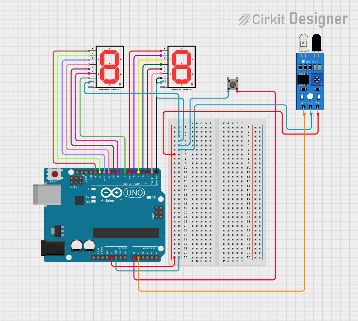
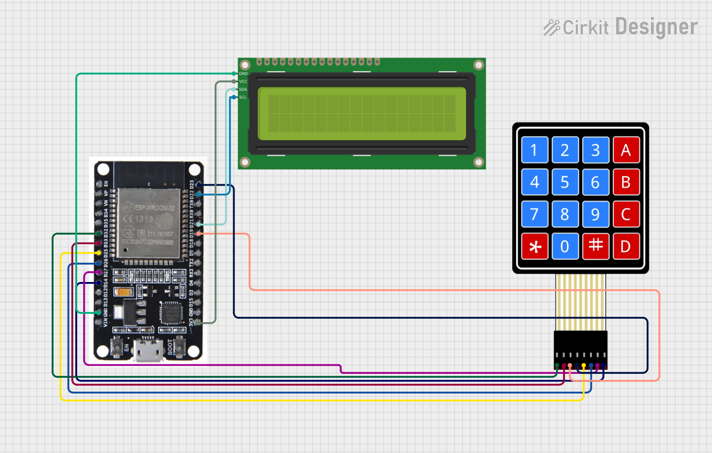
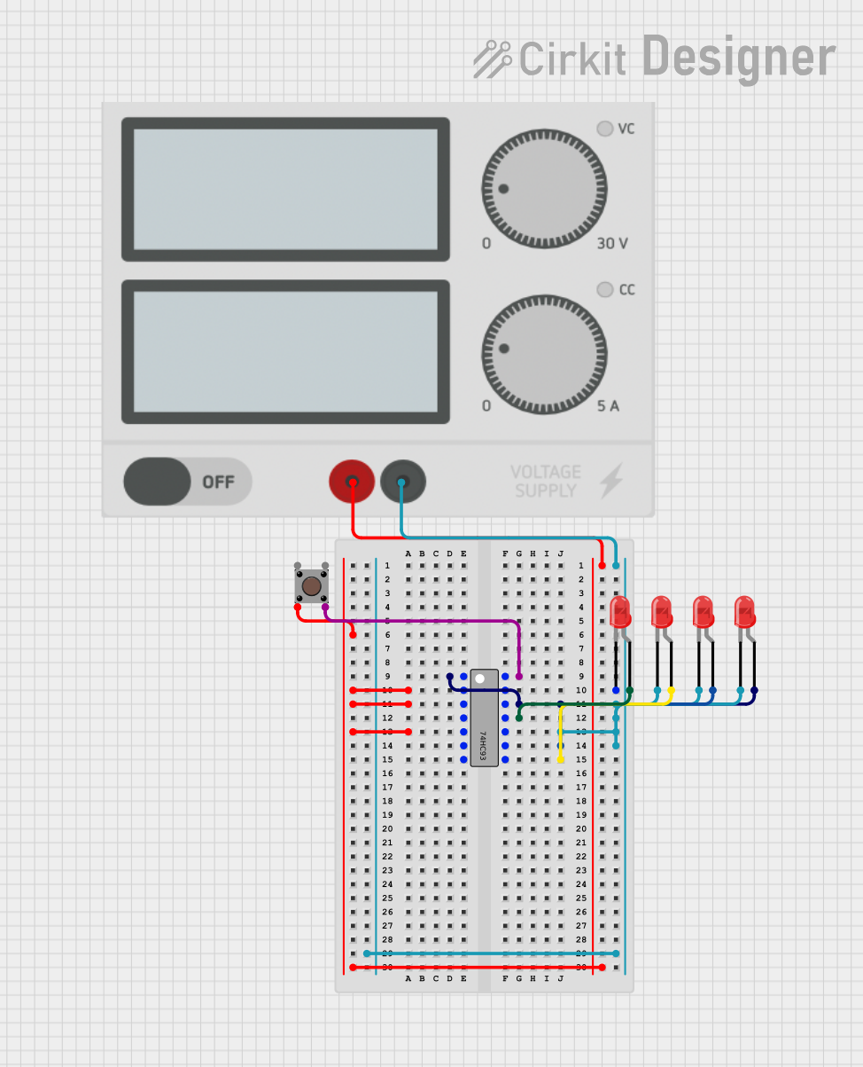
Explore Projects Built with counter
Technical Specifications
Key Technical Details
- Type: Synchronous or Asynchronous
- Counting Sequence: Binary, BCD (Binary Coded Decimal), or custom
- Input Signal: Clock pulse or event signal
- Output: Binary count
- Voltage Ratings: Typically 3.3V or 5V for TTL (Transistor-Transistor Logic) counters, may vary for CMOS (Complementary Metal-Oxide-Semiconductor) counters
- Current Ratings: Depends on the specific counter IC (Integrated Circuit)
- Power Ratings: Varies with technology and speed of operation
Pin Configuration and Descriptions
| Pin Number | Name | Description |
|---|---|---|
| 1 | CLK | Clock input; increments the counter on the rising/falling edge |
| 2 | RST | Reset input; resets the counter to zero when activated |
| 3-10 | Q0-Q7 | Output pins; represent the binary count |
| 11 | EN | Enable input; allows counting when high |
| 12 | CTEN | Count enable; when low, the counter is disabled |
| 13 | Vcc | Positive supply voltage |
| 14 | GND | Ground connection |
Note: The actual pin configuration may vary depending on the specific counter IC. Always refer to the manufacturer's datasheet for exact details.
Usage Instructions
How to Use the Counter in a Circuit
- Power Supply: Connect the Vcc pin to the positive supply voltage and the GND pin to the ground.
- Clock Input: Apply the clock signal to the CLK pin. Ensure that the voltage levels of the clock signal are compatible with the counter's logic levels.
- Reset: Connect the RST pin to a control signal or a push-button to enable resetting the counter to its initial state.
- Enable Counting: If the counter has an EN or CTEN pin, ensure it is set to the appropriate logic level to enable counting.
- Output Monitoring: Connect the output pins Q0-Q7 to the rest of the circuit or to a display to monitor the count.
Important Considerations and Best Practices
- Debounce Inputs: If using mechanical switches for reset or count inputs, ensure they are debounced to prevent erroneous counts.
- Power Decoupling: Place a decoupling capacitor close to the Vcc and GND pins to stabilize the power supply.
- Clock Signal Integrity: Use a clean and stable clock signal to prevent glitches in counting.
- Heat Dissipation: Provide adequate heat sinking if the counter operates at high frequencies or in high-power applications.
Troubleshooting and FAQs
Common Issues
- Counter Not Incrementing: Ensure the clock signal is clean and within the specified voltage range. Check if the EN or CTEN pin is correctly set.
- Erratic Counting: This could be due to noise or bouncing on the clock input. Verify the integrity of the clock signal and use debouncing techniques if necessary.
- Counter Resets Unexpectedly: Check for noise on the reset line or ensure that the reset circuit is functioning correctly.
Solutions and Tips
- Use Pull-Up/Pull-Down Resistors: To avoid floating inputs, use pull-up or pull-down resistors on the control pins.
- Check Power Supply: Verify that the power supply is stable and within the specified range for the counter.
- Refer to Datasheet: For specific troubleshooting related to the counter IC, consult the manufacturer's datasheet.
Example Code for Arduino UNO
// Example code for interfacing a binary counter with an Arduino UNO

const int clockPin = 2; // Connect to the CLK pin of the counter
const int resetPin = 3; // Connect to the RST pin of the counter

void setup() {
  pinMode(clockPin, OUTPUT);
  pinMode(resetPin, OUTPUT);

  // Reset the counter at the start
  digitalWrite(resetPin, HIGH);
  delay(10);
  digitalWrite(resetPin, LOW);
}

void loop() {
  // Generate a clock pulse
  digitalWrite(clockPin, HIGH);
  delay(10); // Wait for 10 milliseconds
  digitalWrite(clockPin, LOW);
  delay(1000); // Wait for 1 second before the next count

  // Reset the counter after 10 counts
  // This part of the code assumes a 4-bit counter for simplicity
  static int count = 0;
  if (++count == 10) {
    digitalWrite(resetPin, HIGH);
    delay(10);
    digitalWrite(resetPin, LOW);
    count = 0;
  }
}
Note: The above code is a simple demonstration of how to interface a counter with an Arduino UNO. The actual implementation may vary based on the specific counter IC and the application requirements. Always refer to the counter's datasheet for precise information on interfacing and operation.