Cirkit Designer Logo
Cirkit Designer
Your all-in-one circuit design IDE
Home / 
Component Documentation

How to Use Gy-33: Examples, Pinouts, and Specs

Image of Gy-33
Cirkit Designer LogoDesign with Gy-33 in Cirkit Designer

Introduction

The GY-33 is a compact gyroscope sensor designed for measuring angular velocity and orientation. It is widely used in applications such as robotics, motion tracking, drone stabilization, and gaming devices. The sensor provides precise measurements of rotational motion, making it an essential component in systems requiring accurate orientation data.

The GY-33 is known for its small size, low power consumption, and ease of integration with microcontrollers, making it a popular choice for both hobbyists and professionals.

Explore Projects Built with Gy-33

Use Cirkit Designer to design, explore, and prototype these projects online. Some projects support real-time simulation. Click "Open Project" to start designing instantly!
ADXL335 Accelerometer Data Visualization with Oscilloscope
Image of SYS Circuit: A project utilizing Gy-33 in a practical application
This circuit connects an AITrip ADXL335 GY-61 accelerometer to an oscilloscope for signal visualization and a 3xAA battery pack for power. The accelerometer's Z-axis output is directly monitored on the oscilloscope, allowing for real-time observation of acceleration changes along that axis. The circuit is likely used for educational or testing purposes to demonstrate how the accelerometer responds to motion.
Cirkit Designer LogoOpen Project in Cirkit Designer
ESP32 and Nextion Touch LCD-Based Thermal Imaging System with GY-MCU90640
Image of Thermal Camera: A project utilizing Gy-33 in a practical application
This circuit integrates an ESP32 microcontroller with a GY-MCU90640 thermal camera and a Nextion Touch LCD display. The ESP32 collects thermal data from the GY-MCU90640 and communicates it to the Nextion display for visualization. Power and ground connections are appropriately managed to ensure proper operation of all components.
Cirkit Designer LogoOpen Project in Cirkit Designer
ESP32-Based Accident Detection and GPS Tracking System with GSM Notifications
Image of hello: A project utilizing Gy-33 in a practical application
This circuit features an ESP32 microcontroller interfaced with an MPU6050 accelerometer/gyroscope, a Neo 6M GPS module, and a SIM800L GSM module. The ESP32 communicates with the MPU6050 via I2C (SCL and SDA lines) to detect potential accidents based on acceleration thresholds, with the GPS module providing location data via a serial connection (RX0 and TX0). The SIM800L GSM module is connected to the ESP32 through another serial interface (RX2 and TX2) to send SMS alerts with location information in case of an accident detection.
Cirkit Designer LogoOpen Project in Cirkit Designer
Battery-Powered Sumo Robot with IR Sensors and DC Motors
Image of MASSIVE SUMO AUTO BOARD: A project utilizing Gy-33 in a practical application
This circuit is designed for a robotic system, featuring a Massive Sumo Board as the central controller. It integrates multiple FS-80NK diffuse IR sensors and IR line sensors for obstacle detection and line following, respectively, and controls two GM25 DC motors via MD13s motor drivers for movement. Power is supplied by an 11.1V LiPo battery.
Cirkit Designer LogoOpen Project in Cirkit Designer

Explore Projects Built with Gy-33

Use Cirkit Designer to design, explore, and prototype these projects online. Some projects support real-time simulation. Click "Open Project" to start designing instantly!
Image of SYS Circuit: A project utilizing Gy-33 in a practical application
ADXL335 Accelerometer Data Visualization with Oscilloscope
This circuit connects an AITrip ADXL335 GY-61 accelerometer to an oscilloscope for signal visualization and a 3xAA battery pack for power. The accelerometer's Z-axis output is directly monitored on the oscilloscope, allowing for real-time observation of acceleration changes along that axis. The circuit is likely used for educational or testing purposes to demonstrate how the accelerometer responds to motion.
Cirkit Designer LogoOpen Project in Cirkit Designer
Image of Thermal Camera: A project utilizing Gy-33 in a practical application
ESP32 and Nextion Touch LCD-Based Thermal Imaging System with GY-MCU90640
This circuit integrates an ESP32 microcontroller with a GY-MCU90640 thermal camera and a Nextion Touch LCD display. The ESP32 collects thermal data from the GY-MCU90640 and communicates it to the Nextion display for visualization. Power and ground connections are appropriately managed to ensure proper operation of all components.
Cirkit Designer LogoOpen Project in Cirkit Designer
Image of hello: A project utilizing Gy-33 in a practical application
ESP32-Based Accident Detection and GPS Tracking System with GSM Notifications
This circuit features an ESP32 microcontroller interfaced with an MPU6050 accelerometer/gyroscope, a Neo 6M GPS module, and a SIM800L GSM module. The ESP32 communicates with the MPU6050 via I2C (SCL and SDA lines) to detect potential accidents based on acceleration thresholds, with the GPS module providing location data via a serial connection (RX0 and TX0). The SIM800L GSM module is connected to the ESP32 through another serial interface (RX2 and TX2) to send SMS alerts with location information in case of an accident detection.
Cirkit Designer LogoOpen Project in Cirkit Designer
Image of MASSIVE SUMO AUTO BOARD: A project utilizing Gy-33 in a practical application
Battery-Powered Sumo Robot with IR Sensors and DC Motors
This circuit is designed for a robotic system, featuring a Massive Sumo Board as the central controller. It integrates multiple FS-80NK diffuse IR sensors and IR line sensors for obstacle detection and line following, respectively, and controls two GM25 DC motors via MD13s motor drivers for movement. Power is supplied by an 11.1V LiPo battery.
Cirkit Designer LogoOpen Project in Cirkit Designer

Technical Specifications

Below are the key technical details of the GY-33 gyroscope sensor:

  • Operating Voltage: 3.3V to 5V
  • Communication Interface: I2C
  • Measurement Range: ±250, ±500, ±1000, ±2000 degrees per second (configurable)
  • Sensitivity: Configurable based on the measurement range
  • Power Consumption: Low power mode available
  • Operating Temperature: -40°C to +85°C
  • Dimensions: Compact form factor (typically 15mm x 15mm)

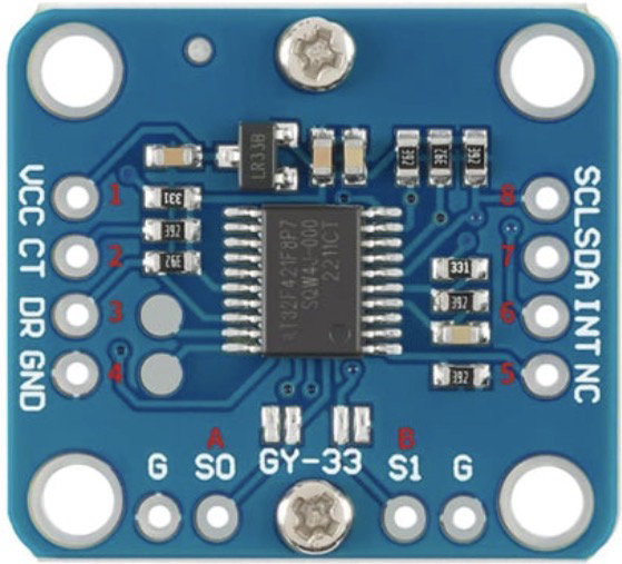
Pin Configuration and Descriptions

The GY-33 module typically has the following pinout:

Pin Name Description
VCC Power supply input (3.3V to 5V)
GND Ground
SDA I2C data line
SCL I2C clock line
INT Interrupt pin (optional, for motion detection)

Usage Instructions

How to Use the GY-33 in a Circuit

  1. Power the Sensor: Connect the VCC pin to a 3.3V or 5V power source and the GND pin to ground.
  2. Connect to a Microcontroller: Use the SDA and SCL pins to connect the GY-33 to the I2C pins of your microcontroller. For an Arduino UNO, connect:
    • SDA to A4
    • SCL to A5
  3. Optional Interrupt: If you need motion detection, connect the INT pin to a digital input pin on your microcontroller.
  4. Pull-Up Resistors: Ensure that the I2C lines (SDA and SCL) have pull-up resistors (typically 4.7kΩ) if not already included on the module.

Important Considerations and Best Practices

  • I2C Address: The default I2C address of the GY-33 is typically 0x68. Check the datasheet or module documentation for confirmation.
  • Calibration: Perform sensor calibration to ensure accurate readings, especially in applications requiring high precision.
  • Mounting: Secure the sensor firmly to avoid vibrations that could affect measurements.
  • Power Supply: Use a stable power source to minimize noise in the sensor readings.

Example Code for Arduino UNO

Below is an example code snippet to read data from the GY-33 using the Arduino Wire library:

#include <Wire.h>

#define GY33_ADDRESS 0x68 // Default I2C address of the GY-33

void setup() {
  Wire.begin(); // Initialize I2C communication
  Serial.begin(9600); // Start serial communication for debugging

  // Wake up the GY-33 (if in sleep mode)
  Wire.beginTransmission(GY33_ADDRESS);
  Wire.write(0x6B); // Power management register
  Wire.write(0x00); // Set to normal mode
  Wire.endTransmission();

  Serial.println("GY-33 Initialized");
}

void loop() {
  Wire.beginTransmission(GY33_ADDRESS);
  Wire.write(0x43); // Starting register for gyroscope data
  Wire.endTransmission(false);
  Wire.requestFrom(GY33_ADDRESS, 6); // Request 6 bytes (X, Y, Z data)

  if (Wire.available() == 6) {
    int16_t gyroX = (Wire.read() << 8) | Wire.read(); // Combine high and low bytes
    int16_t gyroY = (Wire.read() << 8) | Wire.read();
    int16_t gyroZ = (Wire.read() << 8) | Wire.read();

    // Print gyroscope data
    Serial.print("Gyro X: "); Serial.print(gyroX);
    Serial.print(" | Gyro Y: "); Serial.print(gyroY);
    Serial.print(" | Gyro Z: "); Serial.println(gyroZ);
  }

  delay(500); // Delay for readability
}

Notes on the Code

  • The code initializes the GY-33 and reads raw gyroscope data from the X, Y, and Z axes.
  • You may need to scale the raw data based on the configured sensitivity of the sensor.

Troubleshooting and FAQs

Common Issues

  1. No Data from the Sensor

    • Ensure the SDA and SCL connections are correct.
    • Verify that the I2C address matches the sensor's default or configured address.
    • Check for proper pull-up resistors on the I2C lines.
  2. Inaccurate Readings

    • Perform sensor calibration to account for offsets and noise.
    • Ensure the sensor is mounted securely to avoid vibrations.
  3. I2C Communication Errors

    • Check the wiring for loose connections.
    • Ensure the microcontroller and sensor share a common ground.

FAQs

Q: Can the GY-33 be used with 5V logic microcontrollers?
A: Yes, the GY-33 is compatible with both 3.3V and 5V logic levels.

Q: How do I change the measurement range of the sensor?
A: The measurement range can be configured by writing to the appropriate register in the sensor's configuration. Refer to the sensor's datasheet for details.

Q: Do I need external pull-up resistors for I2C?
A: Many GY-33 modules include built-in pull-up resistors. If not, you will need to add external resistors (typically 4.7kΩ) to the SDA and SCL lines.

By following this documentation, you should be able to successfully integrate and use the GY-33 gyroscope sensor in your projects.