How to Use BD10KA5WF-E2: Examples, Pinouts, and Specs
Introduction
The BD10KA5WF-E2 is a high-power switching transistor designed for use in power supply circuits and motor control applications. This component is known for its reliability and efficiency in controlling high-current loads. It is commonly used in DC-DC converters, power management systems, and as a switch for various types of motors.
Explore Projects Built with BD10KA5WF-E2


Explore Projects Built with BD10KA5WF-E2
Technical Specifications
Key Technical Details
- Output Voltage Range: 1.0 V to 5.5 V (adjustable)
- Maximum Output Current: 1 A
- Input Voltage Range: 5.5 V to 16 V
- Quiescent Current: 15 µA (typ.)
- Dropout Voltage: 0.5 V (max.)
- Operating Temperature Range: -40°C to +105°C
- Package: HTSOP-J8
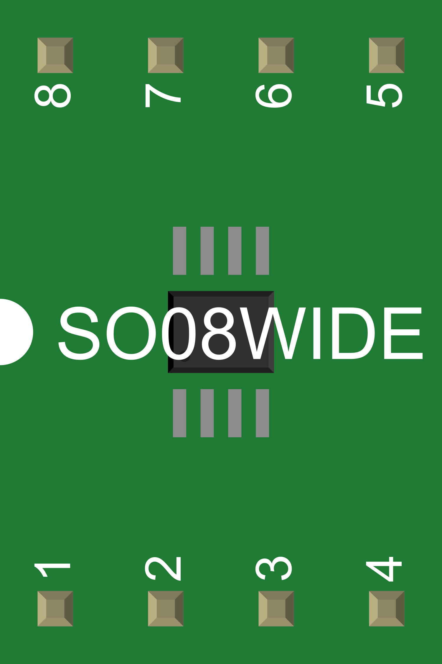
Pin Configuration and Descriptions
| Pin Number | Name | Description |
|---|---|---|
| 1 | VIN | Input voltage pin. Connect to the power source. |
| 2 | GND | Ground pin. Connect to the system ground. |
| 3 | VOUT | Regulated output voltage pin. Connect to the load. |
| 4 | EN | Enable pin. Drive high to turn on the regulator. |
| 5 | FB | Feedback pin. Connect to the output through a voltage divider for voltage regulation. |
| 6 | NC | No connection. This pin is not internally connected. |
| 7 | NC | No connection. This pin is not internally connected. |
| 8 | NC | No connection. This pin is not internally connected. |
Usage Instructions
How to Use the BD10KA5WF-E2 in a Circuit
- Power Source Connection: Connect the VIN pin to a power source that is within the specified input voltage range.
- Ground Connection: Connect the GND pin to the system ground.
- Load Connection: Connect the VOUT pin to the load that requires a regulated voltage.
- Enable the Regulator: Drive the EN pin high to enable the regulator. When the EN pin is low, the regulator is in a shutdown mode.
- Setting Output Voltage: Connect a voltage divider from VOUT to FB to GND to set the output voltage. The output voltage can be adjusted by changing the ratio of the resistors in the voltage divider.
Important Considerations and Best Practices
- Ensure that the input voltage does not exceed the maximum rating to prevent damage to the component.
- Use capacitors at the input and output for stability. Typically, a 10 µF ceramic capacitor at the input and a 22 µF ceramic capacitor at the output are recommended.
- Avoid placing high heat-generating components near the BD10KA5WF-E2 to maintain thermal performance.
- Ensure proper PCB layout for heat dissipation and minimal noise/interference in the circuit.
Troubleshooting and FAQs
Common Issues
- Output Voltage Fluctuation: This can be caused by insufficient input voltage or incorrect feedback resistor values. Check the input voltage and resistor values in the voltage divider.
- Device Overheating: Overheating may occur if the current exceeds the maximum rating or if there is inadequate heat sinking. Ensure proper current limits and heat dissipation measures are in place.
- Regulator Not Enabling: If the regulator does not turn on, check the EN pin voltage and ensure it is being driven high.
Solutions and Tips for Troubleshooting
- Verify all connections and ensure that the pins are correctly wired.
- Check the input and output capacitors for proper value and placement.
- Use a multimeter to measure the voltage at the EN pin, VOUT pin, and VIN pin to ensure they are within the specified ranges.
- If the device is not functioning as expected, replace it with a new one to rule out the possibility of a faulty component.
FAQs
Q: Can the BD10KA5WF-E2 be used with an Arduino UNO? A: Yes, it can be used with an Arduino UNO or any other microcontroller to control power to various loads, provided the input voltage and current requirements are met.
Q: What is the maximum current the BD10KA5WF-E2 can handle? A: The maximum output current is 1 A. Ensure that the load does not exceed this rating.
Q: How do I adjust the output voltage? A: The output voltage is adjusted by changing the resistor values in the voltage divider connected from VOUT to FB to GND.
Example Arduino UNO Code
// Define the enable pin for the BD10KA5WF-E2
const int enablePin = 7;

void setup() {
  // Set the enable pin as an output
  pinMode(enablePin, OUTPUT);
}

void loop() {
  // Turn on the BD10KA5WF-E2
  digitalWrite(enablePin, HIGH);
  delay(5000); // Keep the regulator on for 5 seconds

  // Turn off the BD10KA5WF-E2
  digitalWrite(enablePin, LOW);
  delay(5000); // Keep the regulator off for 5 seconds
}
Note: The above code is a simple example to demonstrate turning the BD10KA5WF-E2 on and off using an Arduino UNO. The actual implementation may vary based on the specific application and circuit design.