How to Use BNO085: Examples, Pinouts, and Specs
Introduction
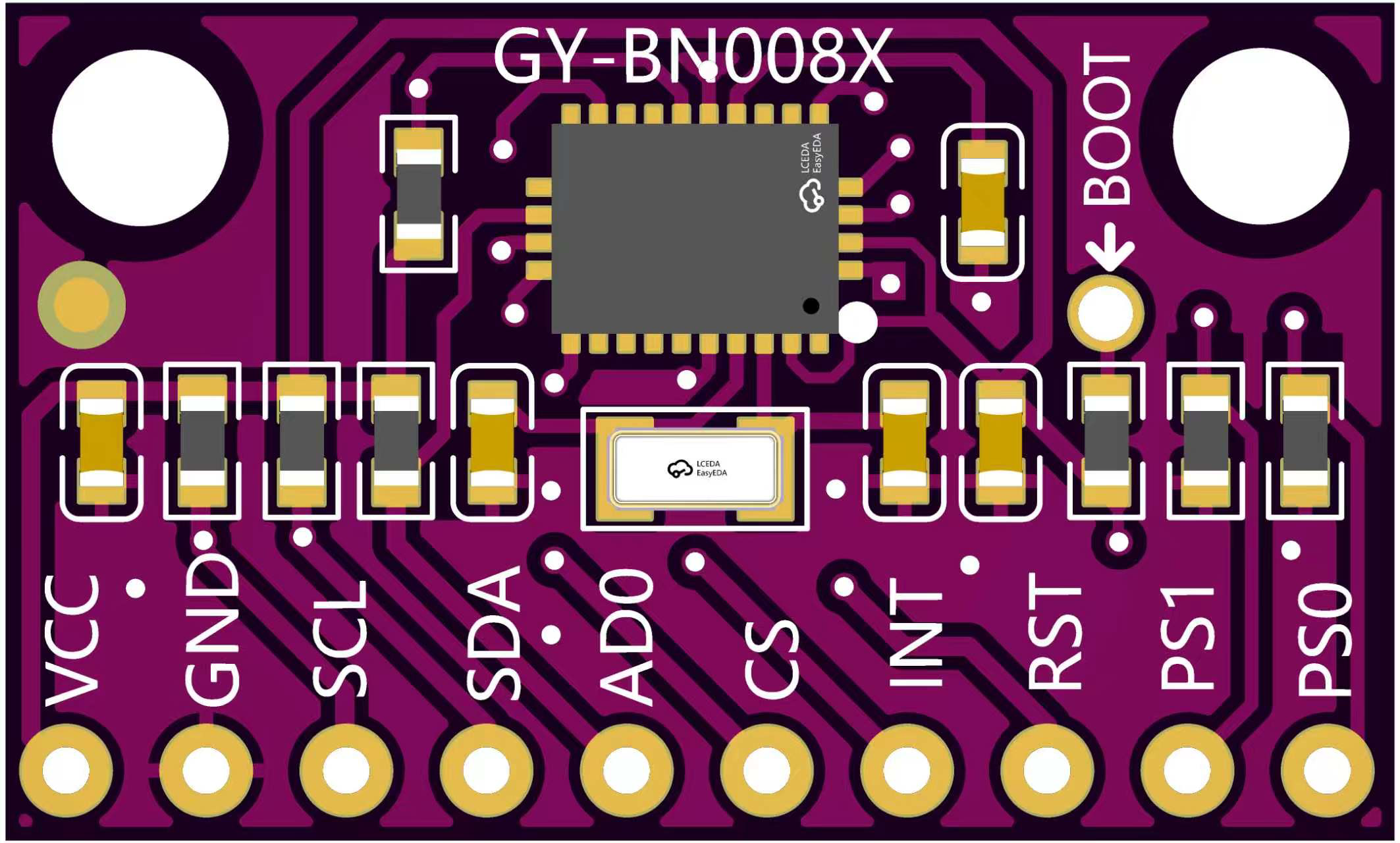
The BNO085, manufactured by 宏维微 (part ID: HW-1002), is a 9-axis absolute orientation sensor that integrates a 3-axis accelerometer, a 3-axis gyroscope, and a 3-axis magnetometer. This sensor is designed to provide precise motion tracking and orientation data, making it ideal for applications in robotics, drones, augmented reality (AR), virtual reality (VR), and wearable devices. Its advanced sensor fusion algorithms ensure high accuracy and reliability in dynamic environments.
Explore Projects Built with BNO085


Explore Projects Built with BNO085
Technical Specifications
The following table outlines the key technical details of the BNO085 sensor:
| Parameter | Value |
|---|---|
| Operating Voltage | 2.4V to 3.6V |
| Communication Interfaces | I²C, SPI, UART |
| Maximum I²C Clock Speed | 400 kHz |
| Gyroscope Range | ±2000°/s |
| Accelerometer Range | ±16g |
| Magnetometer Range | ±1300 µT |
| Operating Temperature | -40°C to +85°C |
| Power Consumption | ~1.3 mA (typical, depends on mode) |
| Dimensions | 3.8 mm x 3.8 mm x 0.95 mm |
Pin Configuration and Descriptions
The BNO085 is typically available in a 28-pin LGA package. Below is the pin configuration and description:
| Pin Number | Pin Name | Description |
|---|---|---|
| 1 | VDD | Power supply (2.4V to 3.6V) |
| 2 | GND | Ground |
| 3 | SDA | I²C data line |
| 4 | SCL | I²C clock line |
| 5 | CS | Chip select for SPI communication |
| 6 | SDO | SPI data output |
| 7 | SDI | SPI data input |
| 8 | INT | Interrupt output (active low) |
| 9-28 | NC | Not connected (reserved for future use) |
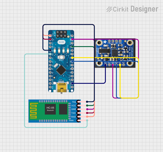
Usage Instructions
How to Use the BNO085 in a Circuit
- Power Supply: Connect the VDD pin to a 3.3V power source and the GND pin to ground.
- Communication Interface: Choose between I²C, SPI, or UART for communication:
- For I²C, connect the SDA and SCL pins to the corresponding lines on your microcontroller. Use pull-up resistors (typically 4.7 kΩ) on both lines.
- For SPI, connect the CS, SDO, and SDI pins to the appropriate SPI lines on your microcontroller.
- For UART, configure the UART pins as per your microcontroller's requirements.
- Interrupt Pin: Optionally, connect the INT pin to a GPIO pin on your microcontroller to handle interrupts.
- Bypass Unused Pins: Leave unused communication pins unconnected or tied to ground as specified in the datasheet.
Important Considerations and Best Practices
- Voltage Levels: Ensure that the voltage levels of the microcontroller match the BNO085's operating voltage (3.3V). Use level shifters if necessary.
- Placement: Mount the sensor on a stable PCB to minimize vibrations and noise.
- Calibration: Perform sensor calibration for accurate readings, especially in environments with magnetic interference.
- Pull-Up Resistors: Use appropriate pull-up resistors for I²C communication to ensure reliable data transfer.
Example Code for Arduino UNO
Below is an example of how to interface the BNO085 with an Arduino UNO using the I²C protocol:
#include <Wire.h>

// BNO085 I2C address
#define BNO085_ADDRESS 0x4A

void setup() {
  Wire.begin(); // Initialize I2C communication
  Serial.begin(9600); // Initialize serial communication for debugging

  // Check if the BNO085 is connected
  Wire.beginTransmission(BNO085_ADDRESS);
  if (Wire.endTransmission() == 0) {
    Serial.println("BNO085 connected successfully!");
  } else {
    Serial.println("Failed to connect to BNO085. Check wiring.");
    while (1); // Halt execution if sensor is not detected
  }

  // Additional initialization code for the BNO085 can be added here
}

void loop() {
  // Request data from the BNO085
  Wire.beginTransmission(BNO085_ADDRESS);
  Wire.write(0x00); // Example register address (replace with actual register)
  Wire.endTransmission(false);
  Wire.requestFrom(BNO085_ADDRESS, 6); // Request 6 bytes of data

  if (Wire.available() == 6) {
    int16_t x = Wire.read() | (Wire.read() << 8); // Read X-axis data
    int16_t y = Wire.read() | (Wire.read() << 8); // Read Y-axis data
    int16_t z = Wire.read() | (Wire.read() << 8); // Read Z-axis data

    // Print the data to the serial monitor
    Serial.print("X: "); Serial.print(x);
    Serial.print(" Y: "); Serial.print(y);
    Serial.print(" Z: "); Serial.println(z);
  }

  delay(100); // Delay for stability
}
Troubleshooting and FAQs
Common Issues
Sensor Not Detected:
- Ensure the wiring is correct and matches the chosen communication protocol.
- Verify that the pull-up resistors are properly connected for I²C communication.
- Check the power supply voltage and ensure it is within the specified range.
Inaccurate Readings:
- Perform a full calibration of the sensor.
- Avoid placing the sensor near strong magnetic fields or sources of vibration.
Communication Errors:
- Verify the I²C address or SPI configuration.
- Check for loose connections or damaged wires.
Solutions and Tips
- Debugging Communication: Use a logic analyzer to monitor I²C or SPI signals for troubleshooting.
- Firmware Updates: Check the manufacturer's website for firmware updates or additional resources.
- Environmental Factors: Minimize environmental noise and interference for optimal performance.
By following this documentation, users can effectively integrate the BNO085 into their projects and achieve accurate motion tracking and orientation data.