
How to Use MAX485: Examples, Pinouts, and Specs
 Design with MAX485 in Cirkit Designer
Introduction
The MAX485 is a low-power, half-duplex RS-485 transceiver designed for robust communication over long distances in noisy environments. Manufactured by Arduino, this component is ideal for industrial automation, data acquisition systems, and other applications requiring reliable serial communication. It supports data transmission speeds of up to 2.5 Mbps and operates efficiently with minimal power consumption.
Explore Projects Built with MAX485
 Open Project in Cirkit Designer
 Open Project in Cirkit Designer
 Open Project in Cirkit Designer
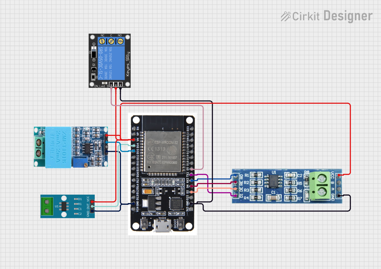 Open Project in Cirkit Designer
Explore Projects Built with MAX485
Open Project in Cirkit DesignerOpen Project in Cirkit DesignerOpen Project in Cirkit DesignerOpen Project in Cirkit DesignerCommon Applications
- Industrial automation and control systems
- Data acquisition and monitoring systems
- Building automation (e.g., HVAC systems)
- Long-distance serial communication
- Networking of microcontrollers and embedded systems
Technical Specifications
The MAX485 is designed to meet the requirements of RS-485 and RS-422 communication standards. Below are its key technical details:
Key Features
- Operating Voltage: 5V DC
- Data Rate: Up to 2.5 Mbps
- Power Consumption: Low-power operation (300 µA typical)
- Communication Mode: Half-duplex
- Input Impedance: 12 kΩ (minimum)
- Driver Output Voltage: ±1.5V (minimum) with a 54Ω load
- Receiver Sensitivity: ±200 mV
- Operating Temperature Range: -40°C to +85°C
- ESD Protection: ±15 kV (Human Body Model)
Pin Configuration and Descriptions
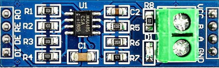
The MAX485 is typically available in an 8-pin DIP or SOIC package. Below is the pinout and description:
| Pin | Name | Type | Description |
|---|---|---|---|
| 1 | RO | Output | Receiver Output: Outputs the received data from the RS-485 bus. |
| 2 | RE̅ | Input | Receiver Enable: Active-low input. Enables the receiver when low. |
| 3 | DE | Input | Driver Enable: Enables the driver when high. |
| 4 | DI | Input | Driver Input: Accepts the data to be transmitted on the RS-485 bus. |
| 5 | GND | Ground | Ground reference for the device. |
| 6 | A | Input/Output | Non-inverting RS-485 bus terminal. |
| 7 | B | Input/Output | Inverting RS-485 bus terminal. |
| 8 | VCC | Power Supply | Power supply input (5V DC). |
Usage Instructions
How to Use the MAX485 in a Circuit
- Power Supply: Connect the VCC pin to a 5V DC power source and the GND pin to the ground.
- Bus Termination: For long-distance communication, use a 120Ω termination resistor between the A and B lines to minimize signal reflections.
- Driver and Receiver Control:
- Set the DE pin high to enable the driver for transmitting data.
- Set the RE̅ pin low to enable the receiver for receiving data.
- Data Transmission:
- Send data to the DI pin for transmission over the RS-485 bus.
- Received data will be output on the RO pin.
- Bus Connections:
- Connect the A and B pins to the corresponding A and B lines of the RS-485 bus.
Important Considerations
- Ensure proper grounding between all devices on the RS-485 bus to avoid communication errors.
- Use twisted-pair cables for the A and B lines to reduce noise and improve signal integrity.
- Avoid enabling both the driver and receiver simultaneously to prevent conflicts in half-duplex communication.
Example: Connecting MAX485 to Arduino UNO
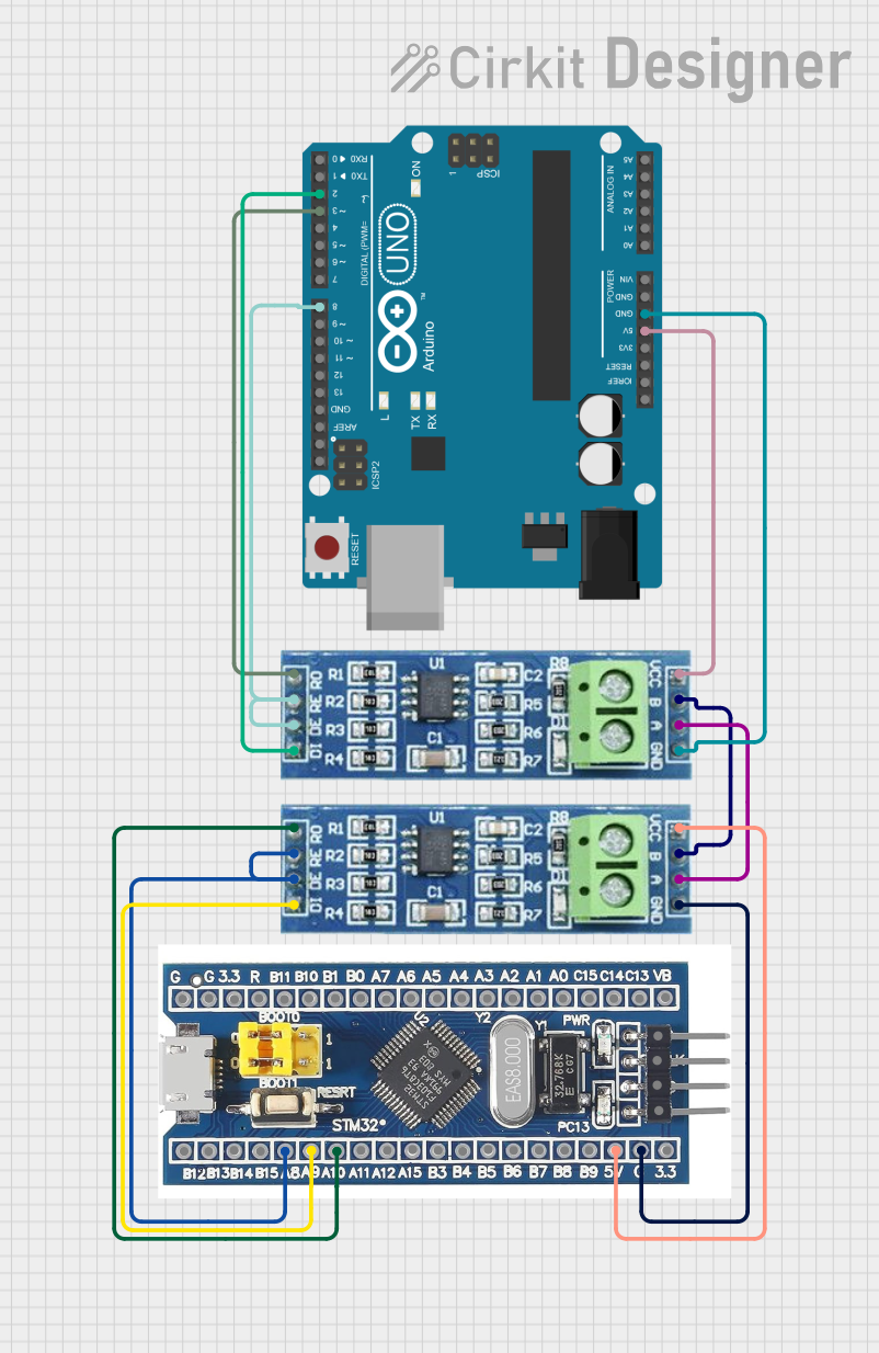
Below is an example of how to connect the MAX485 to an Arduino UNO for serial communication:
Wiring Diagram
- MAX485 Pin RO → Arduino Pin 2 (RX)
- MAX485 Pin DI → Arduino Pin 3 (TX)
- MAX485 Pin DE → Arduino Pin 4
- MAX485 Pin RE̅ → Arduino Pin 4
- MAX485 Pin A → RS-485 Bus A Line
- MAX485 Pin B → RS-485 Bus B Line
- MAX485 Pin VCC → Arduino 5V
- MAX485 Pin GND → Arduino GND
Arduino Code Example
// Include SoftwareSerial library for communication
#include <SoftwareSerial.h>

// Define MAX485 control pins
#define MAX485_DE 4
#define MAX485_RE 4

// Define RX and TX pins for SoftwareSerial
#define RX_PIN 2
#define TX_PIN 3

// Create a SoftwareSerial object
SoftwareSerial RS485Serial(RX_PIN, TX_PIN);

void setup() {
  // Initialize serial communication
  Serial.begin(9600);
  RS485Serial.begin(9600);

  // Set MAX485 control pins as output
  pinMode(MAX485_DE, OUTPUT);
  pinMode(MAX485_RE, OUTPUT);

  // Set MAX485 to receive mode initially
  digitalWrite(MAX485_DE, LOW);
  digitalWrite(MAX485_RE, LOW);

  Serial.println("MAX485 Communication Initialized");
}

void loop() {
  // Example: Send data over RS-485
  digitalWrite(MAX485_DE, HIGH); // Enable driver
  digitalWrite(MAX485_RE, HIGH); // Disable receiver
  RS485Serial.println("Hello, RS-485!");
  delay(1000);

  // Example: Receive data over RS-485
  digitalWrite(MAX485_DE, LOW); // Disable driver
  digitalWrite(MAX485_RE, LOW); // Enable receiver
  if (RS485Serial.available()) {
    String receivedData = RS485Serial.readString();
    Serial.print("Received: ");
    Serial.println(receivedData);
  }
}
Troubleshooting and FAQs
Common Issues
No Communication Between Devices:
- Ensure the A and B lines are correctly connected and terminated with a 120Ω resistor.
- Verify that the DE and RE̅ pins are set correctly for transmitting and receiving.
Data Corruption or Noise:
- Use twisted-pair cables for the A and B lines.
- Check for proper grounding between all devices on the RS-485 bus.
Overheating of the MAX485:
- Verify that the supply voltage does not exceed 5V.
- Ensure the A and B lines are not shorted.
FAQs
Q1: Can the MAX485 be used for full-duplex communication?
A1: No, the MAX485 is designed for half-duplex communication. For full-duplex, consider using a full-duplex RS-485 transceiver like the MAX488.
Q2: What is the maximum communication distance for the MAX485?
A2: The maximum distance depends on the data rate and cable quality. At lower data rates (e.g., 100 kbps), it can communicate over distances up to 1200 meters.
Q3: Can I use the MAX485 with a 3.3V microcontroller?
A3: The MAX485 requires a 5V power supply. However, you can use level shifters to interface it with 3.3V logic.
Q4: How many devices can be connected to the RS-485 bus?
A4: The MAX485 supports up to 32 devices on the same bus. For larger networks, use repeaters or transceivers with higher fan-out capabilities.