How to Use NiceRF LoRa1280-T: Examples, Pinouts, and Specs
Introduction
The NiceRF LoRa1280-T is a low-power, long-range transceiver module that leverages LoRa (Long Range) modulation technology. It is specifically designed for wireless communication in IoT (Internet of Things) applications, offering reliable connectivity over distances of several kilometers while maintaining low power consumption. This module is ideal for applications requiring long-range communication, such as smart agriculture, industrial automation, environmental monitoring, and smart cities.
Explore Projects Built with NiceRF LoRa1280-T


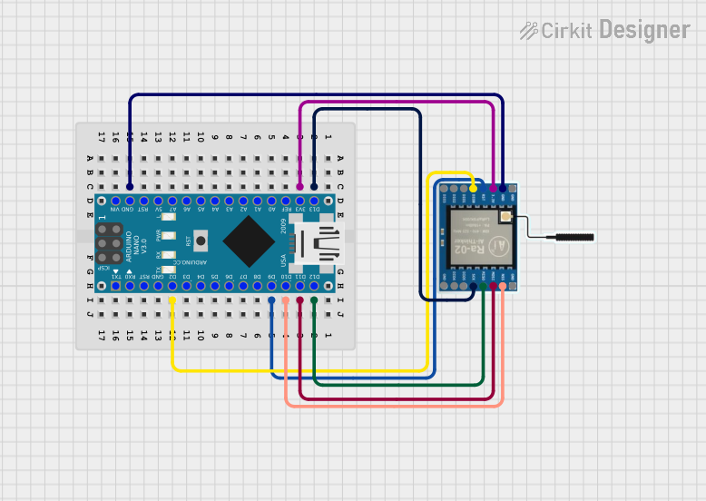
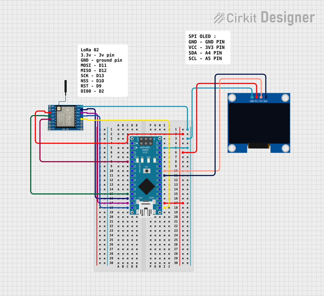
Explore Projects Built with NiceRF LoRa1280-T
Common Applications and Use Cases
- Smart Agriculture: Remote monitoring of soil moisture, weather conditions, and crop health.
- Industrial Automation: Wireless control and monitoring of machinery and equipment.
- Environmental Monitoring: Data collection from remote sensors for air quality, water levels, or weather.
- Smart Cities: Applications like parking management, street lighting control, and waste management.
- Asset Tracking: Long-range tracking of vehicles, goods, or livestock.
Technical Specifications
The NiceRF LoRa1280-T module is built to provide robust performance in a compact form factor. Below are its key technical details:
Key Technical Details
| Parameter | Value |
|---|---|
| Frequency Range | 137 MHz to 1020 MHz |
| Modulation Technology | LoRa (Long Range) |
| Output Power | Up to +20 dBm |
| Sensitivity | -139 dBm (at SF12, 125 kHz bandwidth) |
| Data Rate | 0.018 kbps to 37.5 kbps |
| Supply Voltage | 1.8V to 3.6V |
| Current Consumption | 9.9 mA (transmit mode at +10 dBm) |
| Operating Temperature | -40°C to +85°C |
| Communication Interface | SPI |
| Dimensions | 17 mm x 16 mm x 2.0 mm |
Pin Configuration and Descriptions
The LoRa1280-T module has a total of 16 pins. Below is the pin configuration and their respective functions:
| Pin Number | Pin Name | Description |
|---|---|---|
| 1 | GND | Ground |
| 2 | VCC | Power supply (1.8V to 3.6V) |
| 3 | SCK | SPI clock input |
| 4 | MISO | SPI data output |
| 5 | MOSI | SPI data input |
| 6 | NSS | SPI chip select |
| 7 | DIO0 | Digital I/O pin 0 (interrupt output) |
| 8 | DIO1 | Digital I/O pin 1 |
| 9 | DIO2 | Digital I/O pin 2 |
| 10 | DIO3 | Digital I/O pin 3 |
| 11 | DIO4 | Digital I/O pin 4 |
| 12 | DIO5 | Digital I/O pin 5 |
| 13 | RESET | Reset pin (active low) |
| 14 | ANT | Antenna connection |
| 15 | NC | Not connected |
| 16 | GND | Ground |
Usage Instructions
How to Use the LoRa1280-T in a Circuit
- Power Supply: Connect the VCC pin to a stable power source within the range of 1.8V to 3.6V. Connect the GND pins to the ground of your circuit.
- SPI Communication: Interface the module with a microcontroller (e.g., Arduino UNO) using the SPI pins (SCK, MISO, MOSI, NSS).
- Antenna Connection: Attach a suitable antenna to the ANT pin for optimal signal transmission and reception.
- Reset: Use the RESET pin to initialize the module when required.
- Digital I/O Pins: Configure the DIO pins as needed for interrupts or other functionalities.
Important Considerations and Best Practices
- Antenna Selection: Use an antenna that matches the operating frequency of the module for maximum range and performance.
- Power Supply Filtering: Ensure a clean and stable power supply to avoid noise interference.
- PCB Layout: Keep the antenna trace as short as possible and avoid placing it near noisy components.
- Regulatory Compliance: Ensure compliance with local regulations for frequency usage and transmission power.
Example Code for Arduino UNO
Below is an example of how to interface the LoRa1280-T module with an Arduino UNO using the SPI interface:
#include <SPI.h>

// Define LoRa1280-T SPI pins
#define NSS 10  // Chip select pin
#define RESET 9 // Reset pin
#define DIO0 2  // Interrupt pin

void setup() {
  // Initialize serial communication for debugging
  Serial.begin(9600);
  while (!Serial);

  // Initialize SPI
  SPI.begin();

  // Configure LoRa module pins
  pinMode(NSS, OUTPUT);
  pinMode(RESET, OUTPUT);
  pinMode(DIO0, INPUT);

  // Reset the LoRa module
  digitalWrite(RESET, LOW);
  delay(10);
  digitalWrite(RESET, HIGH);
  delay(10);

  // Initialize LoRa module (example configuration)
  if (!initLoRa()) {
    Serial.println("LoRa initialization failed!");
    while (1);
  }
  Serial.println("LoRa initialized successfully!");
}

void loop() {
  // Example: Send a message
  sendLoRaMessage("Hello, LoRa!");
  delay(2000); // Wait 2 seconds before sending the next message
}

bool initLoRa() {
  // Example function to initialize the LoRa module
  // Add specific initialization commands here
  return true; // Return true if initialization is successful
}

void sendLoRaMessage(String message) {
  // Example function to send a message via LoRa
  digitalWrite(NSS, LOW); // Select the LoRa module
  SPI.transfer(0x00);     // Example command to send data
  for (int i = 0; i < message.length(); i++) {
    SPI.transfer(message[i]); // Send each character
  }
  digitalWrite(NSS, HIGH); // Deselect the LoRa module
  Serial.println("Message sent: " + message);
}
Troubleshooting and FAQs
Common Issues and Solutions
No Communication with the Module:
- Cause: Incorrect SPI connections or configuration.
- Solution: Double-check the wiring and ensure the SPI pins are correctly connected to the microcontroller.
Poor Signal Range:
- Cause: Improper antenna or interference.
- Solution: Use a high-quality antenna and ensure it is tuned to the operating frequency. Avoid placing the module near sources of interference.
Module Not Responding:
- Cause: Incorrect power supply or reset issues.
- Solution: Verify the power supply voltage and ensure the RESET pin is properly configured.
Data Loss or Corruption:
- Cause: High noise levels or incorrect data rate settings.
- Solution: Reduce the data rate for better sensitivity and ensure a clean power supply.
FAQs
Q: Can the LoRa1280-T module be used for bidirectional communication?
A: Yes, the module supports both transmission and reception, making it suitable for bidirectional communication.
Q: What is the maximum range of the LoRa1280-T module?
A: The range depends on environmental conditions and antenna quality. In open areas, it can achieve several kilometers.
Q: Is the module compatible with Arduino boards?
A: Yes, the module can be interfaced with Arduino boards using the SPI interface.
Q: Does the module support encryption?
A: Yes, the LoRa protocol includes built-in encryption for secure communication.