Cirkit Designer Logo
Cirkit Designer
Your all-in-one circuit design IDE
Home / 
Component Documentation

How to Use YDLIDAR GS5 : Examples, Pinouts, and Specs

Image of YDLIDAR GS5
Cirkit Designer LogoDesign with YDLIDAR GS5 in Cirkit Designer

Introduction

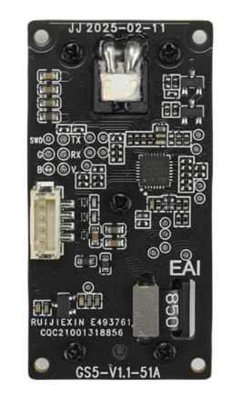
The YDLIDAR GS5 is a 360-degree laser scanner designed for high-precision distance measurement and mapping. Manufactured by YDLIDAR, this compact and lightweight LiDAR sensor is ideal for robotic applications, including autonomous navigation, obstacle detection, and environmental mapping. Its ability to operate effectively in diverse environments makes it a versatile choice for developers and engineers working on robotics, drones, and other automation projects.

Explore Projects Built with YDLIDAR GS5

Use Cirkit Designer to design, explore, and prototype these projects online. Some projects support real-time simulation. Click "Open Project" to start designing instantly!
Solar-Powered GSM/GPRS+GPS Tracker with Seeeduino XIAO
Image of SOS System : A project utilizing YDLIDAR GS5  in a practical application
This circuit features an Ai Thinker A9G development board for GSM/GPRS and GPS/BDS connectivity, interfaced with a Seeeduino XIAO microcontroller for control and data processing. A solar cell, coupled with a TP4056 charging module, charges a 3.3V battery, which powers the system through a 3.3V regulator ensuring stable operation. The circuit likely serves for remote data communication and location tracking, with the capability to be powered by renewable energy and interfaced with additional sensors or input devices via the Seeeduino XIAO.
Cirkit Designer LogoOpen Project in Cirkit Designer
Arduino UNO with A9G GSM/GPRS and Dual VL53L1X Distance Sensors
Image of TED CIRCUIT : A project utilizing YDLIDAR GS5  in a practical application
This circuit features an Arduino UNO microcontroller interfaced with an A9G GSM/GPRS+GPS/BDS module and two VL53L1X time-of-flight distance sensors. The A9G module is connected to the Arduino via serial communication for GPS and GSM functionalities, while both VL53L1X sensors are connected through I2C with shared SDA and SCL lines and individual SHUT pins for selective sensor activation. The Arduino is programmed to control these peripherals, although the specific functionality is not detailed in the provided code.
Cirkit Designer LogoOpen Project in Cirkit Designer
Arduino Nano-Based GPS Tracker with GSM Communication and IR Obstacle Detection
Image of circuit1: A project utilizing YDLIDAR GS5  in a practical application
This circuit features an Arduino Nano interfaced with a SIM800L EVB GSM module for cellular communication, a GPS NEO 6M module for location tracking, and three TCRT 5000 IR sensors for object detection or line tracking. The Arduino facilitates data exchange between the GPS and GSM modules and processes signals from the IR sensors. The provided code skeleton suggests that the Arduino is programmed to perform tasks in a loop, but specific functionality is not detailed in the code.
Cirkit Designer LogoOpen Project in Cirkit Designer
Arduino UNO Based Fall Detection System with GSM Alert
Image of Fall detection and alert: A project utilizing YDLIDAR GS5  in a practical application
This circuit features an Arduino UNO microcontroller interfaced with an Adafruit ADXL345 accelerometer and a SIM800L GSM module. The Arduino monitors the accelerometer for a fall detection event and uses the GSM module to send an SMS alert when a fall is detected. Additionally, there is a blue LED connected through a resistor that could be used for status indication.
Cirkit Designer LogoOpen Project in Cirkit Designer

Explore Projects Built with YDLIDAR GS5

Use Cirkit Designer to design, explore, and prototype these projects online. Some projects support real-time simulation. Click "Open Project" to start designing instantly!
Image of SOS System : A project utilizing YDLIDAR GS5  in a practical application
Solar-Powered GSM/GPRS+GPS Tracker with Seeeduino XIAO
This circuit features an Ai Thinker A9G development board for GSM/GPRS and GPS/BDS connectivity, interfaced with a Seeeduino XIAO microcontroller for control and data processing. A solar cell, coupled with a TP4056 charging module, charges a 3.3V battery, which powers the system through a 3.3V regulator ensuring stable operation. The circuit likely serves for remote data communication and location tracking, with the capability to be powered by renewable energy and interfaced with additional sensors or input devices via the Seeeduino XIAO.
Cirkit Designer LogoOpen Project in Cirkit Designer
Image of TED CIRCUIT : A project utilizing YDLIDAR GS5  in a practical application
Arduino UNO with A9G GSM/GPRS and Dual VL53L1X Distance Sensors
This circuit features an Arduino UNO microcontroller interfaced with an A9G GSM/GPRS+GPS/BDS module and two VL53L1X time-of-flight distance sensors. The A9G module is connected to the Arduino via serial communication for GPS and GSM functionalities, while both VL53L1X sensors are connected through I2C with shared SDA and SCL lines and individual SHUT pins for selective sensor activation. The Arduino is programmed to control these peripherals, although the specific functionality is not detailed in the provided code.
Cirkit Designer LogoOpen Project in Cirkit Designer
Image of circuit1: A project utilizing YDLIDAR GS5  in a practical application
Arduino Nano-Based GPS Tracker with GSM Communication and IR Obstacle Detection
This circuit features an Arduino Nano interfaced with a SIM800L EVB GSM module for cellular communication, a GPS NEO 6M module for location tracking, and three TCRT 5000 IR sensors for object detection or line tracking. The Arduino facilitates data exchange between the GPS and GSM modules and processes signals from the IR sensors. The provided code skeleton suggests that the Arduino is programmed to perform tasks in a loop, but specific functionality is not detailed in the code.
Cirkit Designer LogoOpen Project in Cirkit Designer
Image of Fall detection and alert: A project utilizing YDLIDAR GS5  in a practical application
Arduino UNO Based Fall Detection System with GSM Alert
This circuit features an Arduino UNO microcontroller interfaced with an Adafruit ADXL345 accelerometer and a SIM800L GSM module. The Arduino monitors the accelerometer for a fall detection event and uses the GSM module to send an SMS alert when a fall is detected. Additionally, there is a blue LED connected through a resistor that could be used for status indication.
Cirkit Designer LogoOpen Project in Cirkit Designer

Common Applications and Use Cases

  • Autonomous robot navigation and SLAM (Simultaneous Localization and Mapping)
  • Obstacle detection and avoidance in robotics
  • Environmental mapping and 3D modeling
  • Indoor and outdoor distance measurement
  • Drones and UAVs for terrain mapping

Technical Specifications

The following table outlines the key technical specifications of the YDLIDAR GS5:

Parameter Value
Measurement Range 0.05 m to 25 m
Scanning Frequency 5 Hz to 12 Hz (adjustable)
Angular Resolution 0.18° to 0.36°
Field of View (FOV) 360°
Distance Accuracy ±2 mm (at 1 m)
Laser Wavelength 905 nm (Infrared)
Laser Safety Class Class 1 (Eye-safe)
Communication Interface USB 2.0 / UART
Input Voltage 5 V DC
Power Consumption ≤3 W
Operating Temperature -10°C to 50°C
Dimensions 70 mm × 70 mm × 41 mm
Weight 190 g

Pin Configuration and Descriptions

The YDLIDAR GS5 uses a standard 4-pin interface for communication and power. The pin configuration is as follows:

Pin Name Description
1 VCC Power input (5 V DC)
2 GND Ground
3 TXD UART Transmit Data (to host device)
4 RXD UART Receive Data (from host device)

Usage Instructions

How to Use the YDLIDAR GS5 in a Circuit

  1. Power Supply: Connect the VCC pin to a stable 5 V DC power source and the GND pin to ground.
  2. Communication: Use the TXD and RXD pins to establish a UART connection with a microcontroller, such as an Arduino UNO, or a computer via a USB-to-UART adapter.
  3. Mounting: Secure the GS5 on a stable platform to ensure accurate scanning. Avoid vibrations or unstable surfaces.
  4. Software Setup: Install the YDLIDAR SDK or use compatible libraries to interface with the sensor. The SDK provides tools for data acquisition, visualization, and processing.

Important Considerations and Best Practices

  • Laser Safety: The GS5 uses a Class 1 laser, which is eye-safe under normal operating conditions. However, avoid direct exposure to the laser beam.
  • Environmental Factors: Ensure the sensor is not exposed to excessive dust, moisture, or direct sunlight, as these can affect performance.
  • Power Stability: Use a regulated power supply to prevent voltage fluctuations that could damage the sensor.
  • Data Processing: The GS5 outputs raw distance and angle data. Use SLAM algorithms or mapping software to process the data for navigation or mapping applications.

Example: Connecting to an Arduino UNO

Below is an example of how to connect and use the YDLIDAR GS5 with an Arduino UNO:

Wiring Diagram

YDLIDAR GS5 Pin Arduino UNO Pin
VCC 5V
GND GND
TXD RX (Pin 0)
RXD TX (Pin 1)

Arduino Code Example

#include <SoftwareSerial.h>

// Define RX and TX pins for SoftwareSerial
SoftwareSerial lidarSerial(10, 11); // RX = Pin 10, TX = Pin 11

void setup() {
  Serial.begin(9600); // Initialize Serial Monitor
  lidarSerial.begin(115200); // Initialize LIDAR communication

  Serial.println("YDLIDAR GS5 Initialized");
}

void loop() {
  if (lidarSerial.available()) {
    // Read data from the LIDAR
    String lidarData = lidarSerial.readStringUntil('\n');
    Serial.println("LIDAR Data: " + lidarData); // Print data to Serial Monitor
  }
}

Note: Replace 10 and 11 with the appropriate pins if using different connections. Ensure the baud rate matches the GS5's default UART settings.

Troubleshooting and FAQs

Common Issues and Solutions

  1. No Data Output

    • Cause: Incorrect wiring or baud rate mismatch.
    • Solution: Verify the connections and ensure the UART baud rate is set to 115200.
  2. Inaccurate Measurements

    • Cause: Environmental interference or unstable mounting.
    • Solution: Ensure the sensor is mounted securely and avoid reflective or transparent surfaces in the scanning area.
  3. Device Not Detected

    • Cause: USB driver not installed or faulty cable.
    • Solution: Install the correct USB driver for the YDLIDAR GS5 and check the cable connection.
  4. Intermittent Power Issues

    • Cause: Unstable power supply.
    • Solution: Use a regulated 5 V DC power source with sufficient current capacity.

FAQs

  • Q: Can the GS5 be used outdoors?

    • A: Yes, but avoid direct sunlight and excessive dust, as these can affect performance.
  • Q: What software is compatible with the GS5?

    • A: The YDLIDAR SDK, ROS (Robot Operating System), and other SLAM libraries support the GS5.
  • Q: How do I clean the sensor?

    • A: Use a soft, lint-free cloth to gently clean the sensor's surface. Avoid using liquids or abrasive materials.
  • Q: Can I adjust the scanning frequency?

    • A: Yes, the scanning frequency can be adjusted between 5 Hz and 12 Hz using the YDLIDAR SDK or configuration tools.