How to Use UV Sensors GYML8511: Examples, Pinouts, and Specs
Introduction
The GYML8511 is a UV sensor module manufactured by ROHM Semiconductor. It is designed to detect ultraviolet (UV) light levels and provides an analog voltage output proportional to the intensity of UV radiation. This module is compact, efficient, and easy to integrate into various electronic systems, making it ideal for applications such as:
- UV exposure monitoring for personal health and safety.
- Environmental sensing for weather stations.
- UV index measurement in IoT devices.
- Industrial UV light detection systems.
The GYML8511 is particularly useful in projects requiring real-time UV intensity data, offering a simple interface for both hobbyists and professionals.
Explore Projects Built with UV Sensors GYML8511
Explore Projects Built with UV Sensors GYML8511
Technical Specifications
Key Technical Details
| Parameter | Value |
|---|---|
| Manufacturer | ROHM Semiconductor |
| Part Number | GYML8511 |
| Operating Voltage | 3.0V to 5.5V |
| Output Voltage Range | 0V to 1.1V (typical) |
| UV Wavelength Range | 280 nm to 400 nm (UV-A and UV-B) |
| Operating Temperature | -30°C to +85°C |
| Current Consumption | 300 µA (typical) |
| Dimensions | 21 mm x 13 mm x 2 mm |
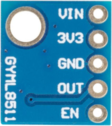
Pin Configuration and Descriptions
The GYML8511 module has a simple pinout, as shown below:
| Pin Name | Pin Number | Description |
|---|---|---|
| VCC | 1 | Power supply input (3.0V to 5.5V). |
| GND | 2 | Ground connection. |
| OUT | 3 | Analog voltage output proportional to UV light. |
Usage Instructions
How to Use the GYML8511 in a Circuit
- Power the Module: Connect the
VCCpin to a 3.3V or 5V power source and theGNDpin to the ground of your circuit. - Read the Output: The
OUTpin provides an analog voltage proportional to the UV intensity. Connect this pin to an analog input pin of a microcontroller (e.g., Arduino) or an ADC (Analog-to-Digital Converter) for measurement. - Calibrate the Sensor: The output voltage corresponds to UV intensity, but you may need to calibrate the sensor for precise UV index measurements based on your application.
Important Considerations and Best Practices
- Avoid Direct Sunlight on the Module: While the sensor is designed to measure UV light, prolonged exposure to direct sunlight may cause overheating or damage.
- Use a Low-Noise Power Supply: To ensure accurate readings, use a stable and low-noise power source.
- Shield from Visible Light: The sensor is sensitive to UV light, but stray visible light may slightly affect readings. Use an appropriate UV filter if necessary.
- Temperature Effects: The sensor operates reliably within its temperature range, but extreme temperatures may affect accuracy.
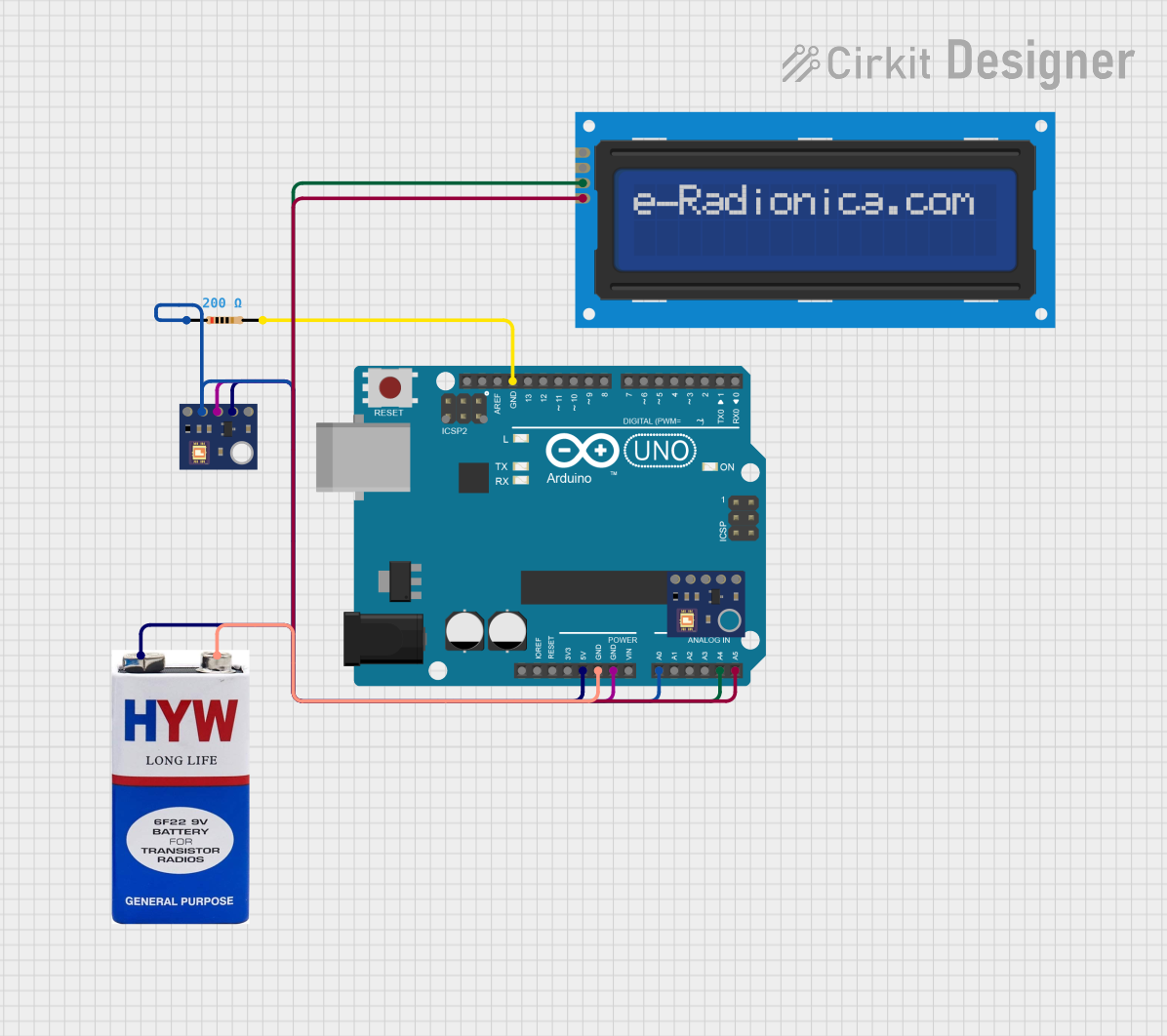
Example: Connecting GYML8511 to Arduino UNO
Below is an example of how to connect and read data from the GYML8511 using an Arduino UNO:
Circuit Diagram
- Connect
VCCto the 3.3V pin on the Arduino. - Connect
GNDto the GND pin on the Arduino. - Connect
OUTto the A0 analog input pin on the Arduino.
Arduino Code
// GYML8511 UV Sensor Example Code
// This code reads the analog output from the GYML8511 and calculates the UV intensity.

const int uvPin = A0; // Analog pin connected to the OUT pin of GYML8511

void setup() {
  Serial.begin(9600); // Initialize serial communication at 9600 baud
  pinMode(uvPin, INPUT); // Set the UV sensor pin as input
}

void loop() {
  int uvAnalogValue = analogRead(uvPin); // Read the analog value from the sensor
  float uvVoltage = uvAnalogValue * (5.0 / 1023.0);
  // Convert the analog value to voltage (assuming 5V reference)

  // Print the UV voltage to the Serial Monitor
  Serial.print("UV Voltage: ");
  Serial.print(uvVoltage);
  Serial.println(" V");

  // Add a delay for stability
  delay(1000); // Wait for 1 second before the next reading
}
Troubleshooting and FAQs
Common Issues and Solutions
No Output Voltage from the Sensor
- Cause: Incorrect wiring or insufficient power supply.
- Solution: Double-check the connections and ensure the
VCCpin is receiving 3.3V to 5V.
Fluctuating or Noisy Readings
- Cause: Electrical noise or unstable power supply.
- Solution: Use a decoupling capacitor (e.g., 0.1 µF) between
VCCandGNDto stabilize the power supply.
Inaccurate UV Measurements
- Cause: Lack of calibration or interference from visible light.
- Solution: Calibrate the sensor using a known UV source and shield it from visible light.
Sensor Overheating
- Cause: Prolonged exposure to direct sunlight or high ambient temperatures.
- Solution: Use the sensor in shaded or controlled environments and ensure proper ventilation.
FAQs
Q: Can the GYML8511 measure UV-C light?
A: No, the GYML8511 is designed to detect UV-A and UV-B light in the 280 nm to 400 nm range. It does not detect UV-C light.
Q: Is the sensor waterproof?
A: No, the GYML8511 is not waterproof. Protect it from moisture and water exposure.
Q: Can I use the GYML8511 with a 3.3V microcontroller?
A: Yes, the GYML8511 operates within a voltage range of 3.0V to 5.5V, making it compatible with 3.3V systems.
Q: How do I convert the output voltage to a UV index?
A: The output voltage is proportional to UV intensity. You can use a calibration formula or reference the sensor's datasheet for conversion details.
This concludes the documentation for the GYML8511 UV Sensor Module. For further assistance, refer to the manufacturer's datasheet or contact technical support.