How to Use Grove EMG Sensor: Examples, Pinouts, and Specs
Introduction
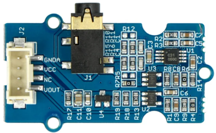
The Grove EMG Sensor is a specialized sensor designed to detect the electrical activity generated by muscle contractions. By measuring these signals, the sensor enables users to monitor muscle activity and control devices based on muscle movement. This makes it an ideal component for applications in biomedical research, prosthetics, robotics, and human-computer interaction.
Explore Projects Built with Grove EMG Sensor
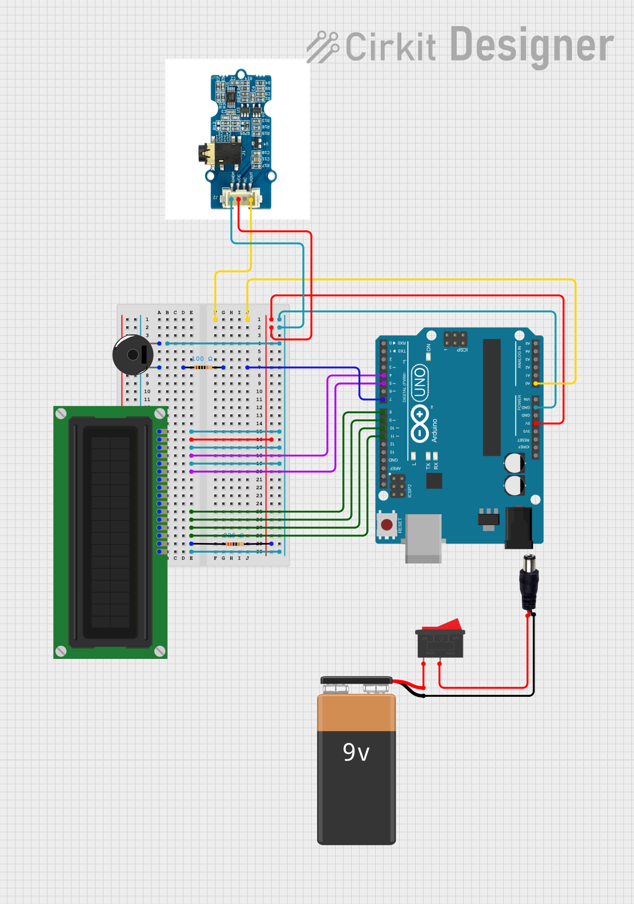

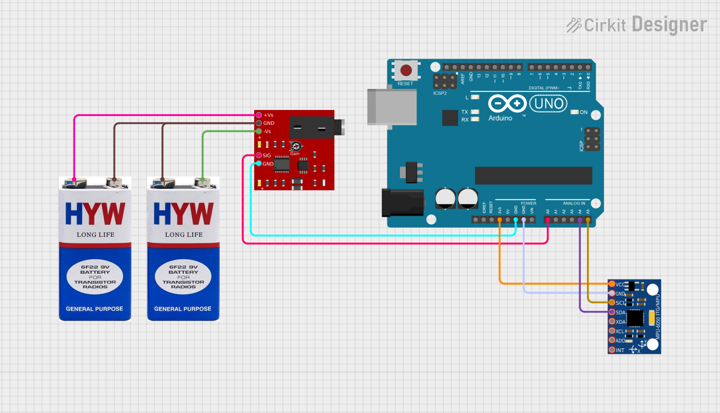
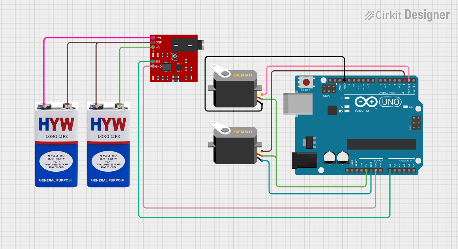
Explore Projects Built with Grove EMG Sensor
Common Applications and Use Cases
- Biomedical signal monitoring and analysis
- Gesture-based control systems
- Prosthetic limb control
- Robotics and wearable technology
- Muscle fatigue detection and rehabilitation systems
Technical Specifications
The following table outlines the key technical details of the Grove EMG Sensor:
| Parameter | Value |
|---|---|
| Manufacturer | Grove |
| Part ID | EMG Sensor |
| Operating Voltage | 3.3V to 5V |
| Output Signal Range | 0.3V to 1.5V (analog output) |
| Operating Current | < 10mA |
| Signal Bandwidth | 20Hz to 500Hz |
| Electrode Cable Length | 100cm |
| Dimensions | 40mm x 20mm |
Pin Configuration and Descriptions
The Grove EMG Sensor has a standard Grove 4-pin interface. The pin configuration is as follows:
| Pin | Name | Description |
|---|---|---|
| 1 | VCC | Power supply input (3.3V to 5V) |
| 2 | GND | Ground connection |
| 3 | SIG | Analog signal output representing muscle activity |
| 4 | NC | Not connected (reserved for future use) |
Usage Instructions
How to Use the Component in a Circuit
Connect the Sensor:
- Use a Grove-compatible cable to connect the sensor to an analog input port on your microcontroller (e.g., Arduino UNO).
- Ensure the VCC and GND pins are properly connected to the power supply and ground, respectively.
Attach the Electrodes:
- Clean the skin surface where the electrodes will be placed to ensure good contact.
- Attach the three electrodes as follows:
- Signal Electrode (Red): Place on the muscle you want to monitor.
- Reference Electrode (Black): Place on a bony area near the muscle.
- Ground Electrode (White): Place on a neutral area, such as the wrist or elbow.
Read the Signal:
- The sensor outputs an analog voltage signal proportional to the muscle activity. This signal can be read using the analog input pin of a microcontroller.
Important Considerations and Best Practices
- Electrode Placement: Proper placement of the electrodes is critical for accurate signal detection. Ensure the skin is clean and free of oils or lotions.
- Signal Noise: To reduce noise, keep the electrode cables away from power lines or other sources of electromagnetic interference.
- Power Supply: Use a stable power supply to avoid fluctuations in the output signal.
- Signal Processing: The raw signal may require filtering or amplification depending on your application.
Example Code for Arduino UNO
The following example demonstrates how to read the EMG signal using an Arduino UNO and display the values in the Serial Monitor:
// Grove EMG Sensor Example Code for Arduino UNO
// This code reads the analog signal from the EMG sensor and prints it to the Serial Monitor.

const int EMG_PIN = A0; // Connect the SIG pin of the sensor to analog pin A0

void setup() {
  Serial.begin(9600); // Initialize serial communication at 9600 baud
  pinMode(EMG_PIN, INPUT); // Set the EMG pin as an input
}

void loop() {
  int emgValue = analogRead(EMG_PIN); // Read the analog value from the sensor
  Serial.print("EMG Signal: "); // Print a label for the signal value
  Serial.println(emgValue); // Print the signal value to the Serial Monitor
  delay(10); // Small delay to stabilize readings
}
Notes:
- The
analogRead()function returns a value between 0 and 1023, corresponding to the voltage range of 0V to 5V (or 3.3V, depending on your microcontroller). - You can process the signal further (e.g., apply filters or thresholds) to suit your application.
Troubleshooting and FAQs
Common Issues and Solutions
No Signal Detected:
- Ensure the electrodes are properly attached to the skin and the sensor is powered.
- Verify that the SIG pin is connected to the correct analog input pin on the microcontroller.
High Noise in the Signal:
- Check for proper electrode placement and ensure the skin is clean.
- Keep the sensor and cables away from sources of electromagnetic interference.
- Use a software or hardware filter to reduce noise.
Fluctuating or Unstable Readings:
- Ensure a stable power supply is used.
- Verify that the ground electrode is securely attached to a neutral area.
FAQs
Q: Can the sensor be used with a 3.3V microcontroller?
A: Yes, the Grove EMG Sensor is compatible with both 3.3V and 5V systems.
Q: How do I process the raw EMG signal?
A: The raw signal can be processed using techniques such as rectification, filtering, and envelope detection to extract meaningful information.
Q: Can I use the sensor for long-term monitoring?
A: Yes, but ensure the electrodes are periodically checked and replaced to maintain good contact and signal quality.
Q: Is the sensor safe for use on the skin?
A: Yes, the sensor is designed for non-invasive use and is safe for skin contact when used as directed.