How to Use Arduino OPTA PLC: Examples, Pinouts, and Specs
Introduction
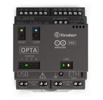
The Arduino OPTA PLC is a compact and versatile programmable logic controller (PLC) designed for industrial automation applications. Manufactured by Arduino, the OPTA PLC combines the simplicity of Arduino programming with the robustness required for industrial environments. It features built-in connectivity options, including Ethernet, Wi-Fi, and Bluetooth, making it ideal for IoT (Internet of Things) applications. The OPTA PLC is suitable for both beginners and experienced developers, offering a user-friendly platform for creating automation solutions.
Explore Projects Built with Arduino OPTA PLC

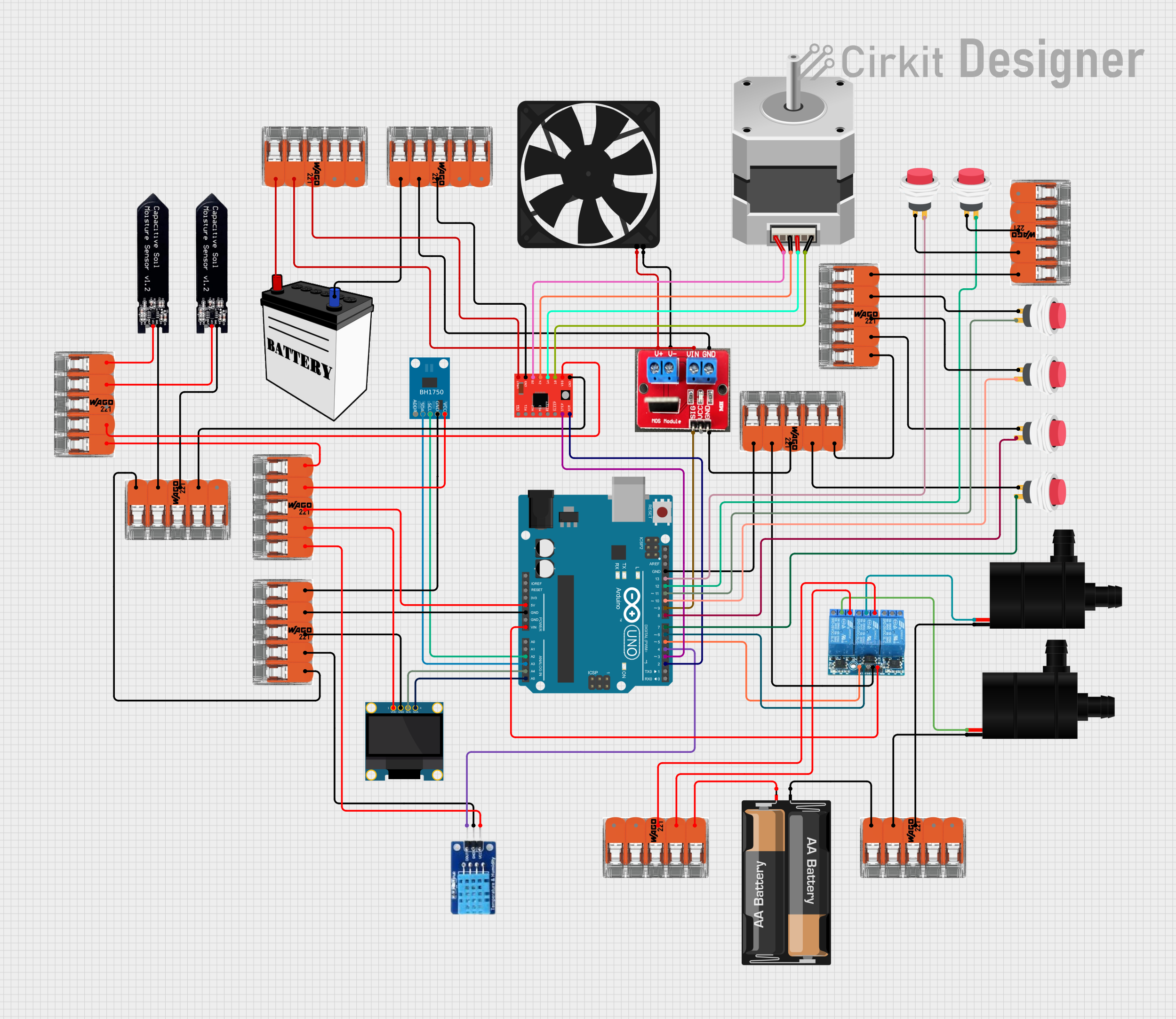

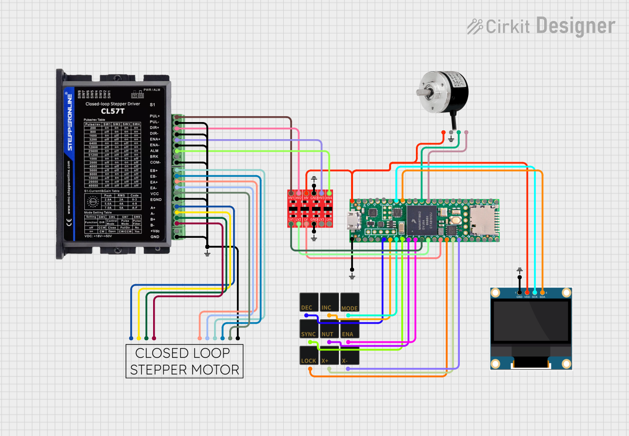
Explore Projects Built with Arduino OPTA PLC
Common Applications and Use Cases
- Industrial automation and process control
- IoT-enabled smart factories
- Home automation systems
- Data logging and monitoring
- Remote device management
- Prototyping and testing of industrial systems
Technical Specifications
Key Technical Details
| Parameter | Specification |
|---|---|
| Manufacturer | Arduino |
| Part ID | OPTA |
| Processor | STM32H747XI dual-core microcontroller (Cortex-M7 @ 480 MHz and Cortex-M4 @ 240 MHz) |
| Memory | 1 MB RAM, 8 MB Flash |
| Connectivity | Ethernet, Wi-Fi, Bluetooth, RS485 |
| Digital Inputs | 8 opto-isolated inputs (24V DC) |
| Digital Outputs | 8 relay outputs (250V AC / 30V DC, 5A max per channel) |
| Analog Inputs | 4 analog inputs (0-10V, 12-bit resolution) |
| Power Supply | 12-24V DC |
| Operating Temperature | -20°C to 60°C |
| Dimensions | 122 x 90 x 56 mm |
| Programming Environment | Arduino IDE, PLC IDE (IEC 61131-3 compliant) |
Pin Configuration and Descriptions
Digital Inputs
| Pin | Description | Voltage Range | Notes |
|---|---|---|---|
| DI1 | Digital Input 1 | 24V DC | Opto-isolated |
| DI2 | Digital Input 2 | 24V DC | Opto-isolated |
| DI3 | Digital Input 3 | 24V DC | Opto-isolated |
| DI4 | Digital Input 4 | 24V DC | Opto-isolated |
| DI5 | Digital Input 5 | 24V DC | Opto-isolated |
| DI6 | Digital Input 6 | 24V DC | Opto-isolated |
| DI7 | Digital Input 7 | 24V DC | Opto-isolated |
| DI8 | Digital Input 8 | 24V DC | Opto-isolated |
Digital Outputs
| Pin | Description | Voltage Range | Current Rating |
|---|---|---|---|
| DO1 | Digital Output 1 (Relay) | 250V AC / 30V DC | 5A max |
| DO2 | Digital Output 2 (Relay) | 250V AC / 30V DC | 5A max |
| DO3 | Digital Output 3 (Relay) | 250V AC / 30V DC | 5A max |
| DO4 | Digital Output 4 (Relay) | 250V AC / 30V DC | 5A max |
| DO5 | Digital Output 5 (Relay) | 250V AC / 30V DC | 5A max |
| DO6 | Digital Output 6 (Relay) | 250V AC / 30V DC | 5A max |
| DO7 | Digital Output 7 (Relay) | 250V AC / 30V DC | 5A max |
| DO8 | Digital Output 8 (Relay) | 250V AC / 30V DC | 5A max |
Analog Inputs
| Pin | Description | Voltage Range | Resolution |
|---|---|---|---|
| AI1 | Analog Input 1 | 0-10V | 12-bit |
| AI2 | Analog Input 2 | 0-10V | 12-bit |
| AI3 | Analog Input 3 | 0-10V | 12-bit |
| AI4 | Analog Input 4 | 0-10V | 12-bit |
Usage Instructions
How to Use the Arduino OPTA PLC in a Circuit
- Power Supply: Connect a 12-24V DC power supply to the power input terminals of the OPTA PLC.
- Digital Inputs: Connect sensors or switches to the digital input terminals (DI1-DI8). Ensure the input voltage is within the 24V DC range.
- Digital Outputs: Connect actuators, relays, or other devices to the digital output terminals (DO1-DO8). Ensure the load does not exceed the maximum current rating of 5A per channel.
- Analog Inputs: Connect analog sensors (e.g., temperature or pressure sensors) to the analog input terminals (AI1-AI4). Ensure the input voltage is within the 0-10V range.
- Programming: Use the Arduino IDE or PLC IDE to write and upload your program to the OPTA PLC via USB or Ethernet.
Important Considerations and Best Practices
- Isolation: Ensure proper isolation between high-voltage and low-voltage circuits to prevent damage to the PLC.
- Load Ratings: Do not exceed the maximum current and voltage ratings for the digital outputs.
- Grounding: Properly ground the PLC to avoid electrical noise and ensure stable operation.
- Firmware Updates: Regularly check for firmware updates from Arduino to ensure optimal performance and security.
- Debugging: Use the built-in debugging tools in the Arduino IDE to troubleshoot your program.
Example Code for Arduino IDE
Below is an example code snippet to toggle a relay connected to DO1 based on a digital input (DI1):
// Define pin numbers for digital input and output
const int digitalInputPin = 2;  // DI1 connected to pin 2
const int digitalOutputPin = 3; // DO1 connected to pin 3

void setup() {
  pinMode(digitalInputPin, INPUT);  // Set DI1 as input
  pinMode(digitalOutputPin, OUTPUT); // Set DO1 as output
}

void loop() {
  int inputState = digitalRead(digitalInputPin); // Read the state of DI1

  if (inputState == HIGH) {
    digitalWrite(digitalOutputPin, HIGH); // Turn on relay (DO1)
  } else {
    digitalWrite(digitalOutputPin, LOW);  // Turn off relay (DO1)
  }
}
Troubleshooting and FAQs
Common Issues and Solutions
PLC Not Powering On
- Cause: Incorrect power supply voltage or loose connections.
- Solution: Verify that the power supply is within the 12-24V DC range and check all connections.
Digital Inputs Not Responding
- Cause: Incorrect wiring or incompatible input voltage.
- Solution: Ensure the input voltage is 24V DC and check the wiring for loose connections.
Digital Outputs Not Activating
- Cause: Exceeding the current or voltage rating of the output.
- Solution: Verify that the connected load does not exceed 5A or 250V AC / 30V DC.
Program Not Uploading
- Cause: USB connection issue or incorrect board selection in the Arduino IDE.
- Solution: Check the USB cable and port, and ensure the correct board (Arduino OPTA) is selected in the IDE.
Wi-Fi or Ethernet Connectivity Issues
- Cause: Incorrect network configuration or weak signal.
- Solution: Verify the network settings in your program and ensure a strong Wi-Fi signal or proper Ethernet connection.
FAQs
Q: Can the OPTA PLC be used with third-party sensors and actuators?
A: Yes, as long as the sensors and actuators meet the voltage and current specifications of the OPTA PLC.Q: Is the OPTA PLC compatible with Modbus communication?
A: Yes, the OPTA PLC supports Modbus RTU and Modbus TCP protocols.Q: Can I use the OPTA PLC for real-time data logging?
A: Yes, the OPTA PLC can log data in real-time and transmit it via Ethernet, Wi-Fi, or Bluetooth.Q: Does the OPTA PLC support over-the-air (OTA) updates?
A: Yes, OTA updates are supported for firmware and program updates.Q: What programming languages are supported?
**