How to Use Hub Motor: Examples, Pinouts, and Specs
Introduction
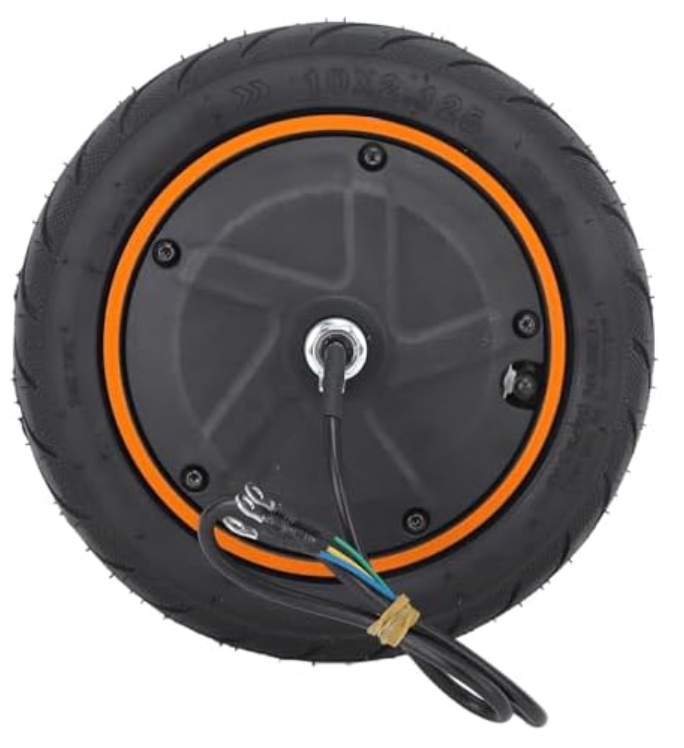
A hub motor is an electric motor integrated directly into the wheel hub of a vehicle, enabling direct drive to the wheel. This design eliminates the need for complex drivetrain components such as chains or belts, making it a highly efficient and compact solution. Hub motors are widely used in electric bicycles, scooters, and other lightweight electric vehicles due to their simplicity, reliability, and ease of installation.
Explore Projects Built with Hub Motor

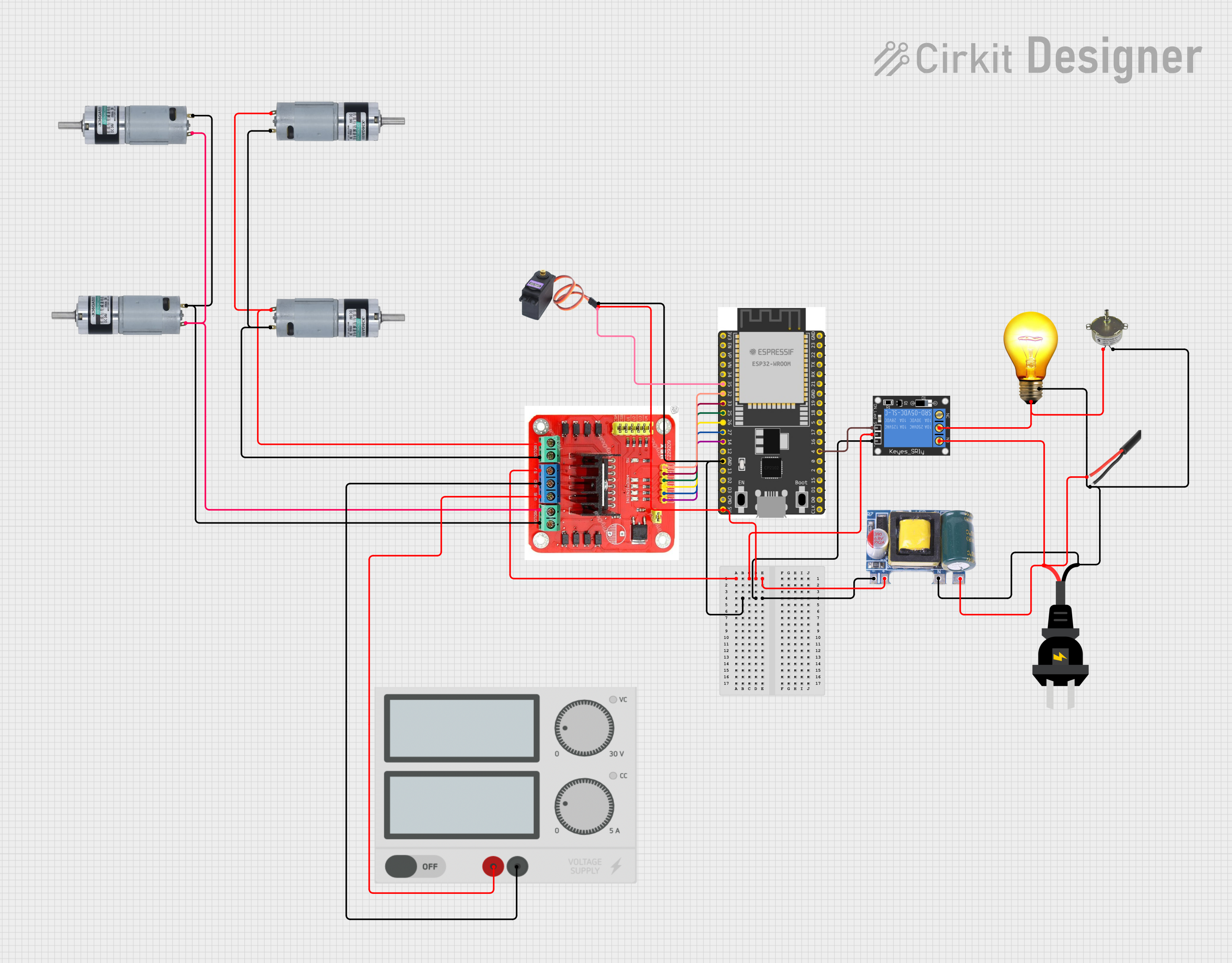
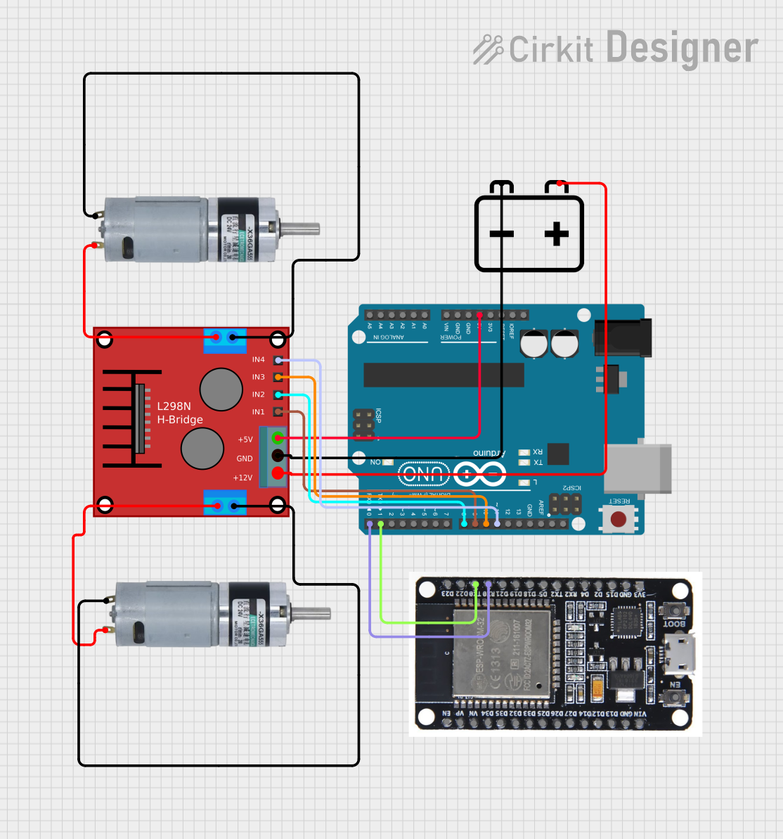

Explore Projects Built with Hub Motor
Common Applications and Use Cases
- Electric bicycles (e-bikes)
- Electric scooters
- Lightweight electric vehicles
- Robotics and automated systems
- DIY electric vehicle projects
Technical Specifications
Below are the general technical specifications for a typical hub motor. Note that specific values may vary depending on the model and manufacturer.
Key Technical Details
| Parameter | Description |
|---|---|
| Voltage Range | 24V - 72V (varies by model) |
| Power Rating | 250W - 2000W (common range) |
| Motor Type | Brushless DC (BLDC) or Brushed DC |
| Torque Output | 10 Nm - 50 Nm (depending on size) |
| Speed | 20 km/h - 60 km/h (varies by application) |
| Efficiency | Up to 90% |
| Weight | 3 kg - 10 kg (depending on size) |
Pin Configuration and Descriptions
Most hub motors, especially brushless DC (BLDC) motors, come with multiple wires for power, control, and feedback. Below is a typical pin configuration:
| Wire Color | Function | Description |
|---|---|---|
| Red | Power (+) | Positive terminal for motor power supply |
| Black | Power (-) | Negative terminal for motor power supply |
| Yellow | Phase A | Motor phase wire A |
| Green | Phase B | Motor phase wire B |
| Blue | Phase C | Motor phase wire C |
| White | Hall Sensor Signal 1 | Feedback signal from Hall sensor 1 |
| Yellow | Hall Sensor Signal 2 | Feedback signal from Hall sensor 2 |
| Green | Hall Sensor Signal 3 | Feedback signal from Hall sensor 3 |
| Black | Hall Sensor Ground | Ground for Hall sensors |
| Red | Hall Sensor Power (+5V) | Power supply for Hall sensors |
Note: The exact wire colors and functions may vary by manufacturer. Always refer to the datasheet or user manual for your specific hub motor.
Usage Instructions
How to Use the Hub Motor in a Circuit
- Power Supply: Ensure the power supply matches the voltage and current requirements of the hub motor. Use a battery or power source capable of delivering sufficient power.
- Motor Controller: Connect the hub motor to a compatible motor controller. The controller regulates power delivery and interprets signals from the Hall sensors.
- Wiring: Follow the pin configuration table to connect the motor wires to the controller. Ensure proper connections for power, phase wires, and Hall sensor signals.
- Throttle or Control Input: Connect a throttle or control input (e.g., potentiometer or microcontroller) to the motor controller to regulate speed and direction.
- Testing: Gradually increase the throttle to test the motor. Monitor for smooth operation and ensure there are no unusual noises or vibrations.
Important Considerations and Best Practices
- Voltage Compatibility: Always use a power supply and controller that match the motor's voltage rating.
- Heat Management: Avoid prolonged operation at maximum power to prevent overheating. Ensure proper ventilation or cooling if necessary.
- Hall Sensor Alignment: If the motor uses Hall sensors, ensure they are properly aligned and connected to avoid erratic behavior.
- Load Conditions: Do not exceed the motor's rated torque or power output to prevent damage.
- Safety: Securely mount the motor to the wheel and ensure all connections are insulated to prevent short circuits.
Example: Using a Hub Motor with Arduino UNO
Below is an example of controlling a hub motor using an Arduino UNO and a motor controller.
// Example code to control a hub motor using Arduino UNO
// This code assumes the motor controller uses a PWM signal for speed control

const int pwmPin = 9;  // PWM pin connected to motor controller
const int dirPin = 8;  // Direction pin connected to motor controller

void setup() {
  pinMode(pwmPin, OUTPUT);  // Set PWM pin as output
  pinMode(dirPin, OUTPUT);  // Set direction pin as output

  // Initialize motor direction and speed
  digitalWrite(dirPin, HIGH);  // Set direction (HIGH = forward, LOW = reverse)
  analogWrite(pwmPin, 0);      // Start with motor off (0% duty cycle)
}

void loop() {
  // Gradually increase motor speed
  for (int speed = 0; speed <= 255; speed += 5) {
    analogWrite(pwmPin, speed);  // Set motor speed (0-255)
    delay(100);                  // Wait 100ms
  }

  // Gradually decrease motor speed
  for (int speed = 255; speed >= 0; speed -= 5) {
    analogWrite(pwmPin, speed);  // Set motor speed (0-255)
    delay(100);                  // Wait 100ms
  }

  // Reverse motor direction
  digitalWrite(dirPin, LOW);  // Change direction to reverse
  delay(1000);                // Wait 1 second before repeating
}
Note: Ensure the motor controller is compatible with PWM signals and the Arduino's voltage levels.
Troubleshooting and FAQs
Common Issues and Solutions
Motor Does Not Spin
- Cause: Incorrect wiring or insufficient power supply.
- Solution: Double-check all connections and ensure the power supply meets the motor's requirements.
Motor Vibrates or Jerks
- Cause: Incorrect phase wire connections or Hall sensor misalignment.
- Solution: Verify the phase wire connections and ensure the Hall sensors are properly connected.
Overheating
- Cause: Prolonged operation at high power or insufficient cooling.
- Solution: Reduce the load on the motor and ensure proper ventilation.
No Response to Throttle
- Cause: Faulty throttle or controller.
- Solution: Test the throttle and controller separately to identify the faulty component.
FAQs
Can I use a hub motor without a controller?
- No, a motor controller is essential for regulating power and interpreting feedback signals.
What type of battery is best for a hub motor?
- Lithium-ion batteries are commonly used due to their high energy density and lightweight design.
How do I determine the correct motor size for my application?
- Consider the required speed, torque, and power output based on your vehicle's weight and intended use.
Can I use a hub motor for robotics projects?
- Yes, hub motors are suitable for robotics applications, especially for wheeled robots requiring direct drive.
By following this documentation, you can effectively integrate and operate a hub motor in your project.