How to Use Reed Switch: Examples, Pinouts, and Specs
Introduction
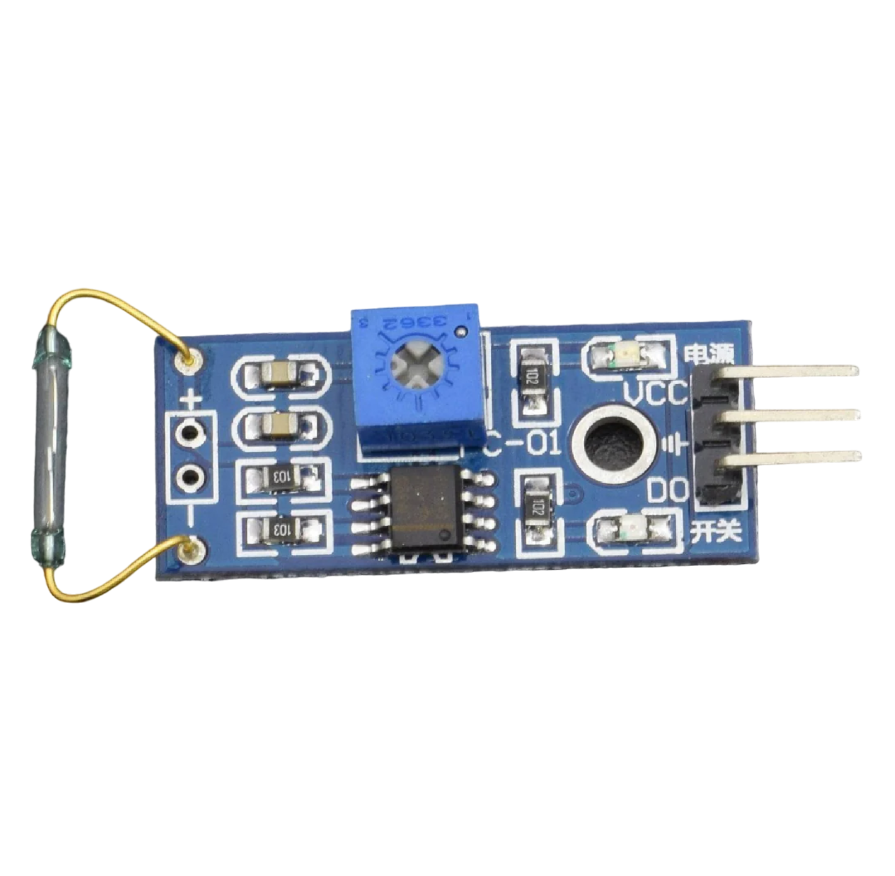
A reed switch is an electromechanical device that operates when exposed to a magnetic field. It consists of two ferromagnetic metal contacts (reeds) in a hermetically sealed glass envelope. The contacts are normally open and close when a magnetic field is applied. Reed switches are used in various applications such as proximity sensing, security systems, and switching circuits.
Explore Projects Built with Reed Switch
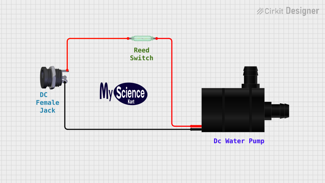
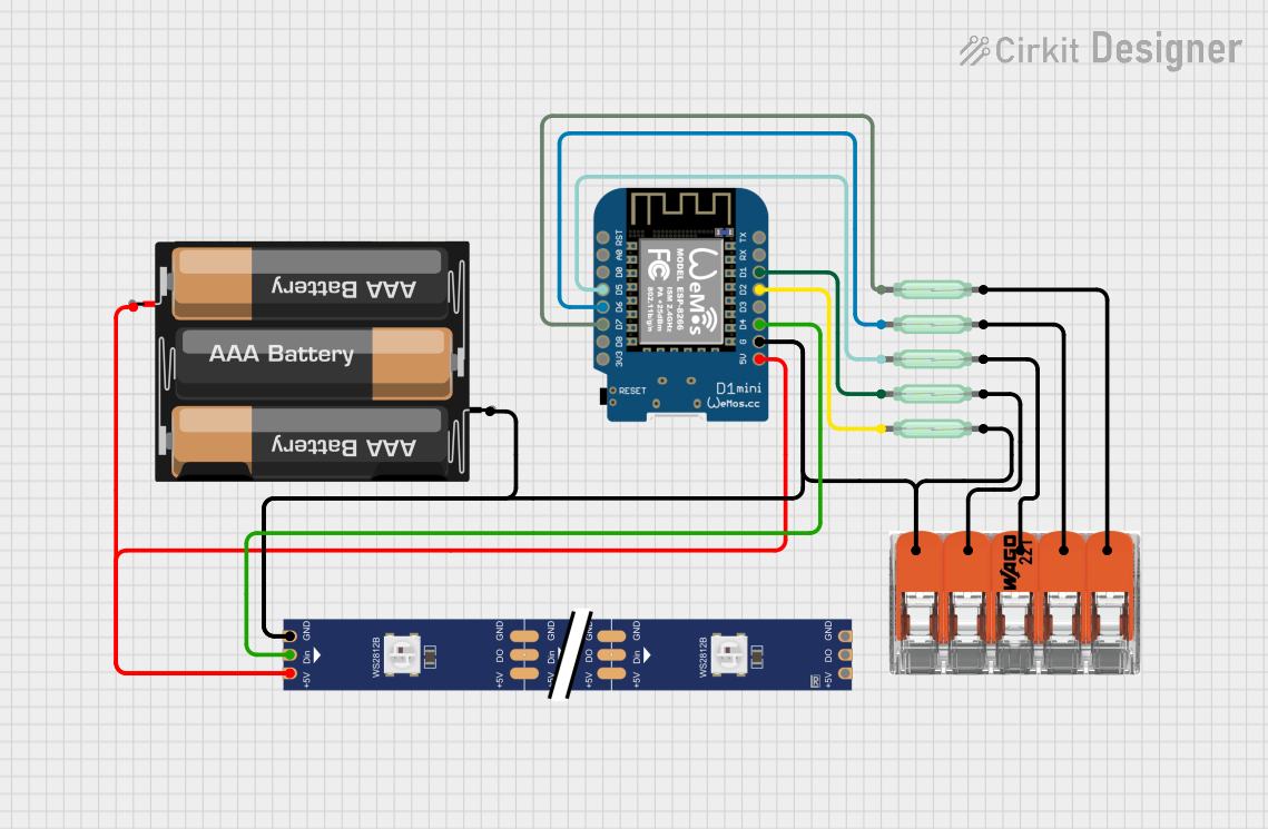
Explore Projects Built with Reed Switch
Common Applications
- Magnetic door and window sensors in security systems
- Position and end limit sensing in industrial controls
- Reed relays for switching high voltages or RF signals
- Keyboard and keypad switches
- Flow metering when paired with a magnetic impeller
Technical Specifications
Key Technical Details
- Switching Voltage: Typically up to 170 VDC
- Switching Current: Up to 0.5 A
- Carry Current: Up to 1.2 A
- Contact Resistance: Typically 150 milliohms or less
- Operate Time: Approximately 0.5 ms
- Release Time: Approximately 0.1 ms
- Operating Temperature: -40°C to +200°C (varies by model)
Pin Configuration and Descriptions
| Pin Number | Description |
|---|---|
| 1 | Reed contact 1 (NC) |
| 2 | Reed contact 2 (NO) |
Note: NC (Normally Closed), NO (Normally Open)
Usage Instructions
How to Use the Reed Switch in a Circuit
- Positioning: Place the reed switch at the desired location where magnetic field presence will be detected.
- Magnet Placement: Position a magnet so that it will come close to the reed switch when the desired event occurs (e.g., a door opening).
- Circuit Integration: Connect the reed switch in series with the load and power source. Ensure that the current and voltage ratings are within the specifications of the reed switch.
- Testing: Test the switch operation by bringing the magnet close to ensure the contacts close.
Important Considerations and Best Practices
- Magnetic Field Strength: Ensure the magnet's field is strong enough to actuate the switch but not so strong that it permanently damages the contacts.
- Mounting: Avoid mechanical stress on the glass envelope.
- Switching Load: Use a snubber circuit if the load is inductive to prevent contact arcing.
- Contact Protection: Consider using a contact protection circuit to extend the life of the reed switch if switching a high load or in a high-frequency application.
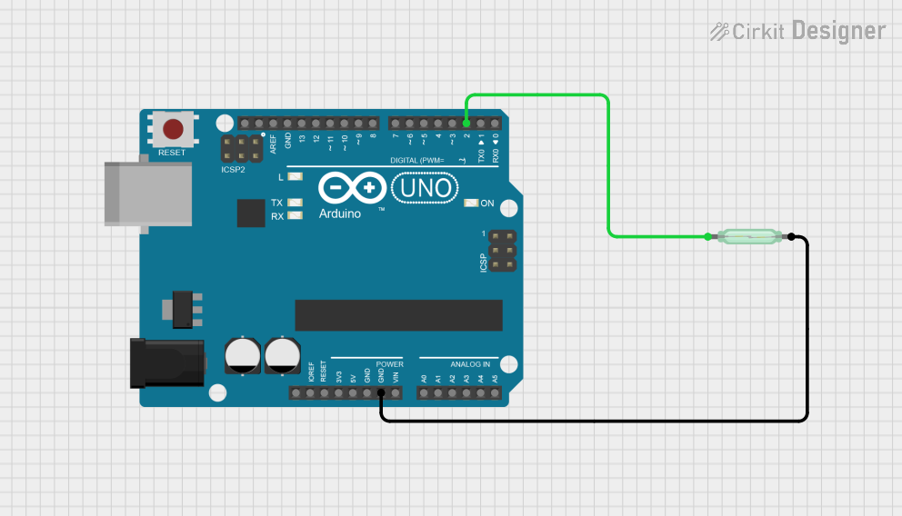
Example Circuit with Arduino UNO
// Example code for using a reed switch with an Arduino UNO

const int reedPin = 2; // Reed switch connected to digital pin 2
const int ledPin = 13; // Onboard LED connected to digital pin 13

void setup() {
  pinMode(reedPin, INPUT_PULLUP); // Initialize reed switch pin as input with internal pull-up
  pinMode(ledPin, OUTPUT); // Initialize LED pin as an output
}

void loop() {
  if (digitalRead(reedPin) == LOW) { // Check if reed switch is closed by magnet
    digitalWrite(ledPin, HIGH); // Turn on LED
  } else {
    digitalWrite(ledPin, LOW); // Turn off LED
  }
}
Note: The internal pull-up resistor is used to ensure a stable state when the switch is open.
Troubleshooting and FAQs
Common Issues
- Switch Does Not Actuate: Verify the magnet's proximity and strength. Check for damage to the reed switch.
- Intermittent Operation: Ensure there is no mechanical vibration affecting the switch. Check for loose connections.
- Shortened Life Span: High switching loads or frequent operation can wear out the contacts. Use appropriate protection circuits.
Solutions and Tips
- Debouncing: Implement software debouncing in the Arduino code to handle mechanical contact bounce.
- Magnetic Interference: Keep other magnetic sources away from the reed switch to prevent false operation.
- Testing: Use a multimeter to check for continuity when the switch is actuated.
FAQs
Q: Can I use a reed switch with AC voltage? A: Yes, but ensure the specifications are within the limits for AC voltage and current.
Q: How can I extend the life of my reed switch? A: Use contact protection circuits, avoid excessive force on the glass envelope, and select a switch with a higher rating than your application requires.
Q: Is there a polarity to a reed switch? A: No, reed switches do not have polarity and can be connected in any direction.