Cirkit Designer Logo
Cirkit Designer
Your all-in-one circuit design IDE
Home / 
Component Documentation

How to Use BL-M8812EU2: Examples, Pinouts, and Specs

Image of BL-M8812EU2
Cirkit Designer LogoDesign with BL-M8812EU2 in Cirkit Designer

Introduction

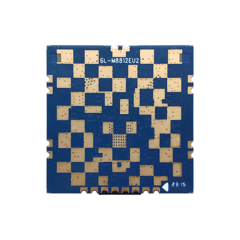
The BL-M8812EU2, manufactured by LB-LINK, is a high-performance, low-power DC motor driver specifically designed for controlling brushless motors. It is ideal for applications requiring precise motor control and high efficiency, such as robotics, industrial automation, and electric vehicles. The component integrates advanced control algorithms, making it suitable for both professional and hobbyist projects.

Explore Projects Built with BL-M8812EU2

Use Cirkit Designer to design, explore, and prototype these projects online. Some projects support real-time simulation. Click "Open Project" to start designing instantly!
ESP8266 NodeMCU with LoRa and RS-485 Communication and Ethernet Connectivity
Image of Wiring Diagram LoRa: A project utilizing BL-M8812EU2 in a practical application
This circuit serves as a multi-protocol communication hub featuring two ESP8266 NodeMCUs for processing, each connected to a LoRa Ra-02 SX1278 for long-range wireless communication. One NodeMCU is also connected to an RS-485 module for serial communication and a W5500 Ethernet module for network connectivity, with MB102 modules supplying power.
Cirkit Designer LogoOpen Project in Cirkit Designer
Satellite-Based Timing and Navigation System with SDR and Atomic Clock Synchronization
Image of GPS 시스템 측정 구성도_Confirm: A project utilizing BL-M8812EU2 in a practical application
This circuit appears to be a complex system involving power supply management, GPS and timing synchronization, and data communication. It includes a SI-TEX G1 Satellite Compass for GPS data, an XHTF1021 Atomic Rubidium Clock for precise timing, and Ettus USRP B200 units for software-defined radio communication. Power is supplied through various SMPS units and distributed via terminal blocks and DC jacks. Data communication is facilitated by Beelink MINI S12 N95 computers, RS232 splitters, and a 1000BASE-T Media Converter for network connectivity. RF Directional Couplers are used to interface antennas with the USRP units, and the entire system is likely contained within cases for protection and organization.
Cirkit Designer LogoOpen Project in Cirkit Designer
WiFi LoRa Environmental Monitoring System with INMP441 Mic and Multiple Sensors
Image of ba_sensing: A project utilizing BL-M8812EU2 in a practical application
This circuit is a solar-powered environmental monitoring system that uses a WiFi LoRa 32V3 microcontroller to collect data from various sensors, including a microphone, UV light sensor, air quality sensor, and temperature/humidity/pressure sensor. The collected data is processed and transmitted via LoRa communication, making it suitable for remote environmental data logging and monitoring applications.
Cirkit Designer LogoOpen Project in Cirkit Designer
Battery-Powered UPS System with Waveshare UPS 3S and Solar Charger
Image of Copy of s: A project utilizing BL-M8812EU2 in a practical application
This circuit is a power management system that integrates a 12V power supply, a solar charger power bank, and multiple Li-ion batteries to provide a stable power output. The Waveshare UPS 3S manages the input from the power sources and batteries, ensuring continuous power delivery. The MRB045 module is used to interface the solar charger with the rest of the system.
Cirkit Designer LogoOpen Project in Cirkit Designer

Explore Projects Built with BL-M8812EU2

Use Cirkit Designer to design, explore, and prototype these projects online. Some projects support real-time simulation. Click "Open Project" to start designing instantly!
Image of Wiring Diagram LoRa: A project utilizing BL-M8812EU2 in a practical application
ESP8266 NodeMCU with LoRa and RS-485 Communication and Ethernet Connectivity
This circuit serves as a multi-protocol communication hub featuring two ESP8266 NodeMCUs for processing, each connected to a LoRa Ra-02 SX1278 for long-range wireless communication. One NodeMCU is also connected to an RS-485 module for serial communication and a W5500 Ethernet module for network connectivity, with MB102 modules supplying power.
Cirkit Designer LogoOpen Project in Cirkit Designer
Image of GPS 시스템 측정 구성도_Confirm: A project utilizing BL-M8812EU2 in a practical application
Satellite-Based Timing and Navigation System with SDR and Atomic Clock Synchronization
This circuit appears to be a complex system involving power supply management, GPS and timing synchronization, and data communication. It includes a SI-TEX G1 Satellite Compass for GPS data, an XHTF1021 Atomic Rubidium Clock for precise timing, and Ettus USRP B200 units for software-defined radio communication. Power is supplied through various SMPS units and distributed via terminal blocks and DC jacks. Data communication is facilitated by Beelink MINI S12 N95 computers, RS232 splitters, and a 1000BASE-T Media Converter for network connectivity. RF Directional Couplers are used to interface antennas with the USRP units, and the entire system is likely contained within cases for protection and organization.
Cirkit Designer LogoOpen Project in Cirkit Designer
Image of ba_sensing: A project utilizing BL-M8812EU2 in a practical application
WiFi LoRa Environmental Monitoring System with INMP441 Mic and Multiple Sensors
This circuit is a solar-powered environmental monitoring system that uses a WiFi LoRa 32V3 microcontroller to collect data from various sensors, including a microphone, UV light sensor, air quality sensor, and temperature/humidity/pressure sensor. The collected data is processed and transmitted via LoRa communication, making it suitable for remote environmental data logging and monitoring applications.
Cirkit Designer LogoOpen Project in Cirkit Designer
Image of Copy of s: A project utilizing BL-M8812EU2 in a practical application
Battery-Powered UPS System with Waveshare UPS 3S and Solar Charger
This circuit is a power management system that integrates a 12V power supply, a solar charger power bank, and multiple Li-ion batteries to provide a stable power output. The Waveshare UPS 3S manages the input from the power sources and batteries, ensuring continuous power delivery. The MRB045 module is used to interface the solar charger with the rest of the system.
Cirkit Designer LogoOpen Project in Cirkit Designer

Common Applications

  • Robotics (e.g., robotic arms, mobile robots)
  • Industrial automation systems
  • Electric vehicles and drones
  • Conveyor belts and automated machinery
  • Home appliances with brushless motors

Technical Specifications

Key Technical Details

Parameter Value
Operating Voltage Range 6V to 24V
Maximum Output Current 2.5A per phase
Control Interface PWM, Direction, and Enable
Motor Type Supported Brushless DC (BLDC) motors
Efficiency Up to 95%
Operating Temperature -20°C to 85°C
Protection Features Overcurrent, Overtemperature,
and Undervoltage Lockout

Pin Configuration and Descriptions

Pin Number Pin Name Description
1 VCC Power supply input (6V to 24V). Connect to the positive terminal of the DC
power source.
2 GND Ground connection. Connect to the negative terminal of the DC power source.
3 PWM Pulse Width Modulation input for speed control. Accepts a PWM signal with
a frequency range of 1kHz to 20kHz.
4 DIR Direction control input. Logic HIGH sets the motor to rotate clockwise,
while logic LOW sets it to rotate counterclockwise.
5 EN Enable input. Logic HIGH enables the motor driver, and logic LOW disables
it.
6, 7, 8 U, V, W Outputs to the three phases of the brushless motor.

Usage Instructions

How to Use the BL-M8812EU2 in a Circuit

  1. Power Supply: Connect the VCC pin to a DC power source within the operating voltage range (6V to 24V). Ensure the power source can supply sufficient current for the motor.
  2. Ground Connection: Connect the GND pin to the ground of the power source and the circuit.
  3. Motor Connections: Connect the U, V, and W pins to the three phases of the brushless motor.
  4. Control Signals:
    • Use a PWM signal on the PWM pin to control the motor speed.
    • Set the DIR pin HIGH or LOW to control the motor's rotation direction.
    • Use the EN pin to enable or disable the motor driver.
  5. Protection: Ensure proper heat dissipation and avoid exceeding the maximum current rating to prevent damage.

Important Considerations and Best Practices

  • Use a decoupling capacitor (e.g., 100µF) near the VCC and GND pins to stabilize the power supply.
  • Ensure the PWM signal frequency is within the specified range (1kHz to 20kHz) for optimal performance.
  • Avoid reversing the power supply polarity, as this may damage the component.
  • If using an Arduino UNO or similar microcontroller, ensure the control signals (PWM, DIR, EN) are within the logic level range (0V to 5V).

Example Arduino Code

Below is an example of how to control the BL-M8812EU2 using an Arduino UNO:

// Define pin connections
const int pwmPin = 9;  // PWM signal pin
const int dirPin = 8;  // Direction control pin
const int enPin = 7;   // Enable pin

void setup() {
  // Set pin modes
  pinMode(pwmPin, OUTPUT);
  pinMode(dirPin, OUTPUT);
  pinMode(enPin, OUTPUT);

  // Initialize motor driver
  digitalWrite(enPin, HIGH);  // Enable the motor driver
  digitalWrite(dirPin, HIGH); // Set direction to clockwise
}

void loop() {
  // Set motor speed using PWM (0 to 255)
  analogWrite(pwmPin, 128); // 50% duty cycle for medium speed
  delay(5000);              // Run for 5 seconds

  // Change direction
  digitalWrite(dirPin, LOW); // Set direction to counterclockwise
  delay(5000);               // Run for 5 seconds
}

Troubleshooting and FAQs

Common Issues and Solutions

  1. Motor Not Spinning:

    • Ensure the EN pin is set to HIGH to enable the motor driver.
    • Verify that the PWM signal is being generated correctly.
    • Check the motor connections (U, V, W) for proper wiring.
  2. Motor Spins in the Wrong Direction:

    • Check the logic level of the DIR pin. Set it HIGH for clockwise rotation and LOW for counterclockwise rotation.
  3. Overheating:

    • Ensure proper heat dissipation by using a heatsink or cooling fan if necessary.
    • Verify that the motor current does not exceed the maximum rating (2.5A per phase).
  4. No Response from the Driver:

    • Check the power supply voltage and ensure it is within the operating range (6V to 24V).
    • Inspect all connections for loose wires or poor soldering.

FAQs

Q1: Can the BL-M8812EU2 drive a brushed DC motor?
A1: No, the BL-M8812EU2 is specifically designed for brushless DC (BLDC) motors and is not compatible with brushed motors.

Q2: What happens if the PWM frequency is outside the specified range?
A2: Operating outside the 1kHz to 20kHz range may result in erratic motor behavior or reduced efficiency.

Q3: Can I use the BL-M8812EU2 with a 3.3V microcontroller?
A3: Yes, but you may need a level shifter to ensure the control signals are compatible with the driver's logic level requirements.

Q4: Does the driver support regenerative braking?
A4: No, the BL-M8812EU2 does not support regenerative braking. Use external circuitry if this feature is required.