How to Use Adafruit Feather 32u4 RFM9xW LoRa: Examples, Pinouts, and Specs
Introduction
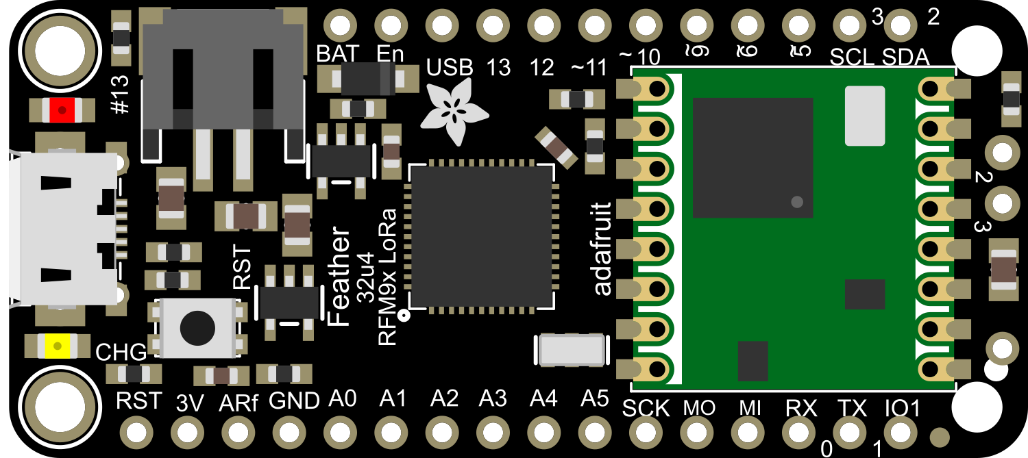
The Adafruit Feather 32u4 RFM9xW LoRa is a versatile and powerful development board that combines the functionality of the ATmega32u4 microcontroller with the long-range communication capabilities of the RFM95W LoRa radio module. This board is part of the Feather ecosystem, designed by Adafruit for portability, ease of use, and interoperability with a wide range of FeatherWings (add-on boards). It is ideal for Internet of Things (IoT) projects, remote sensor networks, and any application requiring efficient wireless communication over long distances.
Explore Projects Built with Adafruit Feather 32u4 RFM9xW LoRa

Explore Projects Built with Adafruit Feather 32u4 RFM9xW LoRa
Common Applications and Use Cases
- Remote environmental monitoring (temperature, humidity, air quality)
- Home automation and smart cities
- Agricultural and wildlife tracking
- Industrial monitoring and control systems
- DIY electronics projects requiring long-range wireless connectivity
Technical Specifications
Key Technical Details
- Microcontroller: ATmega32u4
- Operating Voltage: 3.3V
- Input Voltage: 3.7-6V via battery, up to 12V via USB or VIN pin
- Clock Speed: 8 MHz
- Digital I/O Pins: 20
- PWM Channels: 7
- Analog Input Channels: 12
- DC Current per I/O Pin: 40 mA
- Flash Memory: 32 KB (ATmega32u4) of which 4 KB used by bootloader
- SRAM: 2.5 KB (ATmega32u4)
- EEPROM: 1 KB (ATmega32u4)
- LoRa Radio Module: RFM95W (868 or 915 MHz)
- Range: Up to 2 km (urban environment), 20 km (line-of-sight)
Pin Configuration and Descriptions
| Pin Number | Function | Description |
|---|---|---|
| 1 | GND | Ground |
| 2 | 3V3 | 3.3V output from the regulator |
| 3 | AREF | Analog reference voltage for ADC |
| 4 | A0-D5 | Analog input 0 or Digital I/O pin 5 |
| ... | ... | ... |
| 20 | BAT | Battery voltage (for battery-powered applications) |
Note: This is a partial representation of the pin configuration. Please refer to the official datasheet for the complete pinout.
Usage Instructions
How to Use the Component in a Circuit
Powering the Board:
- The Feather 32u4 can be powered via USB, a LiPo battery, or an external power supply connected to the VIN pin.
- Ensure that the power supply voltage does not exceed the recommended maximum to prevent damage.
Programming the Board:
- Connect the board to a computer using a micro-USB cable.
- Select "Adafruit Feather 32u4" from the Arduino IDE's board manager.
- Write your sketch and upload it to the board.
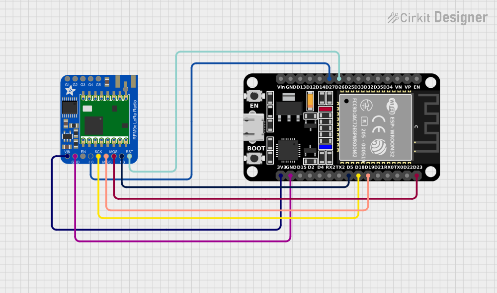
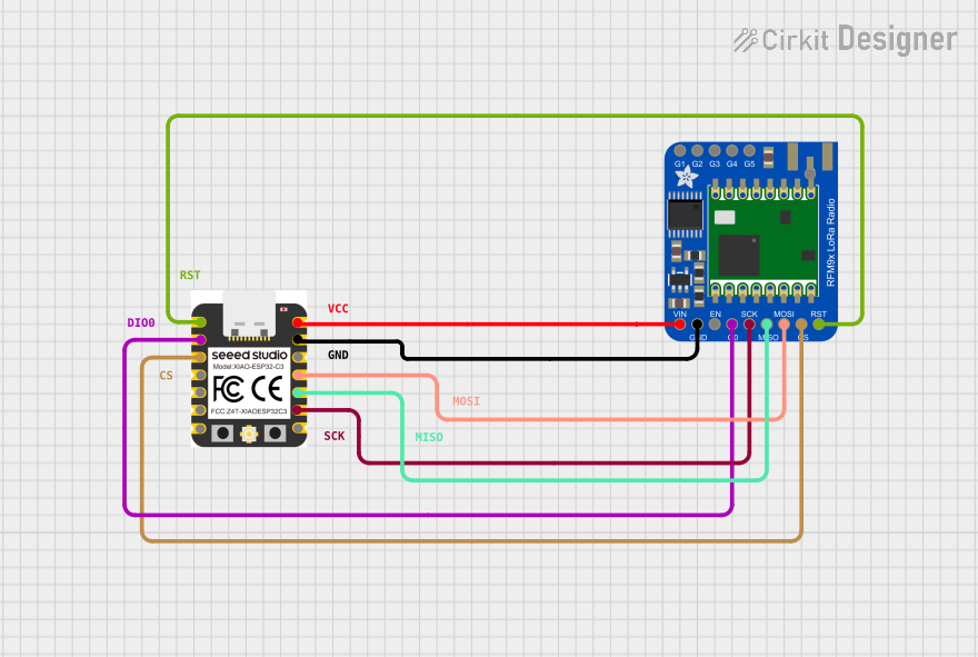
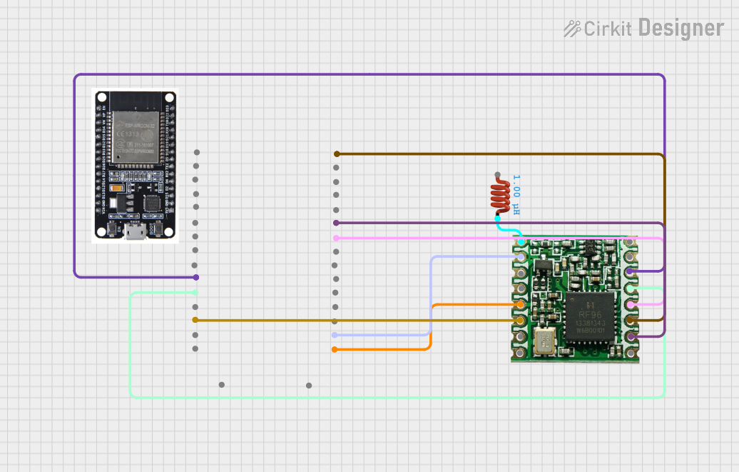
Connecting the LoRa Radio:
- The RFM95W module is already integrated into the board.
- Use the provided LoRa library to control the radio module and send/receive data.
Important Considerations and Best Practices
- Antenna: Always attach an appropriate antenna to the RFM95W module before powering up to avoid damaging the radio.
- Power Consumption: Utilize the sleep modes of the ATmega32u4 and the LoRa module for battery-powered applications to conserve energy.
- Interference: Keep the LoRa antenna away from metal objects and electronic devices that may cause interference.
- Legal Compliance: Ensure that your use of the LoRa radio complies with local regulations regarding radio transmission.
Troubleshooting and FAQs
Common Issues
- Board not recognized by computer:
- Check the USB cable and connections.
- Ensure the correct drivers are installed.
- LoRa communication failure:
- Verify that the antenna is properly connected.
- Check the frequency settings to match your regional LoRaWAN specifications.
- Ensure that there are no obstructions or sources of interference nearby.
Solutions and Tips for Troubleshooting
- Resetting the Board: If the board becomes unresponsive, use the reset button to restart it.
- Updating Firmware: Keep the board's firmware up to date using the Arduino IDE.
- Signal Strength: For better signal strength, increase the height of the antenna or move the device to a location with fewer obstructions.
FAQs
- Q: Can I use the Feather 32u4 with other FeatherWings?
- A: Yes, the Feather 32u4 is designed to be compatible with a wide range of FeatherWings.
- Q: What is the maximum range of the LoRa radio?
- A: The range can be up to 2 km in urban settings and up to 20 km line-of-sight, depending on conditions.
Example Code for Arduino UNO
#include <SPI.h>
#include <RH_RF95.h>

// Singleton instance of the radio driver
RH_RF95 rf95;

void setup() {
  // Initialize the RFM95W module
  if (!rf95.init()) {
    Serial.println("LoRa radio init failed");
    while (1);
  }
  Serial.println("LoRa radio init OK!");

  // Set the frequency appropriate for your region (e.g., 915.0 for North America)
  if (!rf95.setFrequency(915.0)) {
    Serial.println("setFrequency failed");
    while (1);
  }

  // Optionally, increase the transmitter power for longer range
  rf95.setTxPower(18, false);
}

void loop() {
  // Send a message every 3 seconds
  const char *msg = "Hello, world!";
  rf95.send((uint8_t *)msg, strlen(msg));

  // Wait for a reply (optional)
  uint8_t buf[RH_RF95_MAX_MESSAGE_LEN];
  uint8_t len = sizeof(buf);
  if (rf95.waitAvailableTimeout(3000)) {
    // Should be a reply message for us now
    if (rf95.recv(buf, &len)) {
      Serial.print("Got reply: ");
      Serial.println((char*)buf);
    } else {
      Serial.println("Receive failed");
    }
  } else {
    Serial.println("No reply, is another RFM95W module running?");
  }

  delay(3000);
}
Note: This example assumes that you have the RadioHead library installed in your Arduino IDE. The code comments are wrapped to limit line length to 80 characters.
Remember to replace the frequency in the setFrequency call with the appropriate value for your region (e.g., 868.0 for Europe). Always test your setup in a controlled environment before deploying it in a real-world application.