
How to Use Heltec WiFi LoRa 32 V2: Examples, Pinouts, and Specs
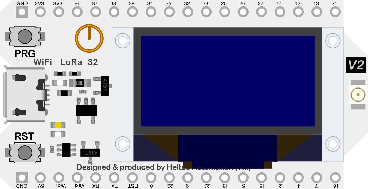
 Design with Heltec WiFi LoRa 32 V2 in Cirkit Designer
Introduction
The Heltec WiFi LoRa 32 V2 is a powerful microcontroller board developed by Heltec Automation. It is based on the ESP32 chip and integrates WiFi, LoRa communication, and a built-in OLED display, making it an excellent choice for IoT (Internet of Things) applications. This board is designed for low-power, long-range wireless communication and is ideal for projects requiring connectivity, data visualization, and sensor integration.
Explore Projects Built with Heltec WiFi LoRa 32 V2
 Open Project in Cirkit Designer
 Open Project in Cirkit Designer
 Open Project in Cirkit Designer
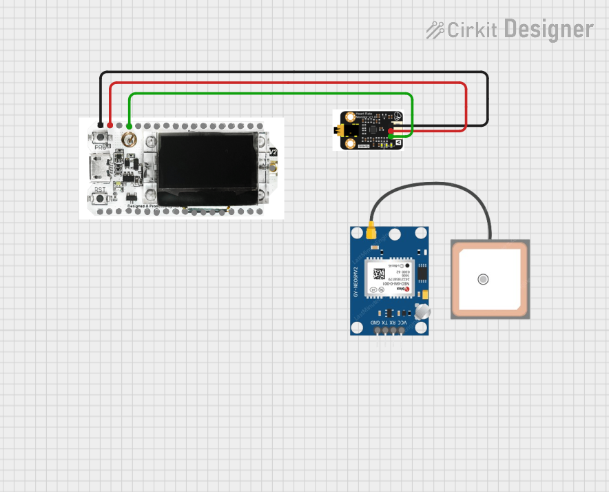 Open Project in Cirkit Designer
Explore Projects Built with Heltec WiFi LoRa 32 V2
Open Project in Cirkit DesignerOpen Project in Cirkit DesignerOpen Project in Cirkit DesignerOpen Project in Cirkit DesignerCommon Applications and Use Cases
- IoT devices and smart home systems
- Environmental monitoring (e.g., temperature, humidity, air quality)
- Remote data logging and telemetry
- Wireless sensor networks
- Industrial automation
- Prototyping LoRa-based communication systems
Technical Specifications
Key Technical Details
| Parameter | Specification |
|---|---|
| Microcontroller | ESP32 (dual-core, 32-bit, Xtensa LX6) |
| Clock Speed | Up to 240 MHz |
| Flash Memory | 8 MB |
| SRAM | 520 KB |
| WiFi | IEEE 802.11 b/g/n |
| LoRa Frequency Bands | 433 MHz, 868 MHz, 915 MHz (region-specific) |
| LoRa Modulation | Semtech SX1276 |
| OLED Display | 0.96-inch, 128x64 pixels, monochrome |
| GPIO Pins | 21 (including ADC, DAC, I2C, SPI, UART, PWM) |
| Operating Voltage | 3.3V |
| Input Voltage Range | 5V (via USB) or 3.3V (via pin) |
| Power Consumption | Low-power mode supported |
| Dimensions | 41 x 25 x 12 mm |
Pin Configuration and Descriptions
| Pin Name | Pin Number | Description |
|---|---|---|
| GND | Multiple | Ground pin |
| 3V3 | Multiple | 3.3V power output |
| VIN | - | Power input (5V via USB or external source) |
| GPIO0 | 0 | General-purpose I/O, boot mode selection |
| GPIO21 | 21 | I2C SDA (data line) |
| GPIO22 | 22 | I2C SCL (clock line) |
| GPIO16 | 16 | OLED reset pin |
| GPIO17 | 17 | UART TX |
| GPIO18 | 18 | SPI SCK |
| GPIO19 | 19 | SPI MISO |
| GPIO23 | 23 | SPI MOSI |
| GPIO25 | 25 | DAC1, PWM output |
| GPIO26 | 26 | DAC2, PWM output |
| GPIO32 | 32 | ADC1, touch sensor |
| GPIO33 | 33 | ADC1, touch sensor |
Usage Instructions
How to Use the Component in a Circuit
Powering the Board:
- Connect the board to a computer or USB power source using a micro-USB cable.
- Alternatively, supply 3.3V to the VIN pin for external power.
Connecting Peripherals:
- Use the GPIO pins to connect sensors, actuators, or other modules.
- For I2C devices, connect SDA to GPIO21 and SCL to GPIO22.
- For SPI devices, use GPIO18 (SCK), GPIO19 (MISO), and GPIO23 (MOSI).
Programming the Board:
- Install the Arduino IDE and add the ESP32 board package.
- Select "Heltec WiFi LoRa 32 V2" from the board manager.
- Write and upload your code via the micro-USB connection.
Using the OLED Display:
- The OLED display is connected to the board via I2C.
- Use libraries like
U8g2orAdafruit_SSD1306to control the display.
Important Considerations and Best Practices
- Ensure the LoRa frequency band matches your region's regulations (e.g., 868 MHz for Europe, 915 MHz for North America).
- Avoid exceeding the maximum current draw of the GPIO pins (12 mA per pin).
- Use level shifters if interfacing with 5V logic devices, as the board operates at 3.3V logic levels.
- For battery-powered applications, enable the low-power mode to conserve energy.
Example Code for Arduino UNO Integration
Below is an example of how to display text on the OLED and send a LoRa message:
#include <Wire.h>
#include <U8g2lib.h>
#include <LoRa.h>

// Initialize the OLED display (I2C address: 0x3C)
U8G2_SSD1306_128X64_NONAME_F_HW_I2C u8g2(U8G2_R0, /* reset=*/ 16, /* clock=*/ 22, /* data=*/ 21);

void setup() {
  // Initialize serial communication
  Serial.begin(115200);

  // Initialize the OLED display
  u8g2.begin();
  u8g2.clearBuffer();
  u8g2.setFont(u8g2_font_ncenB08_tr);
  u8g2.drawStr(0, 10, "Heltec LoRa V2");
  u8g2.sendBuffer();

  // Initialize LoRa communication
  if (!LoRa.begin(915E6)) { // Set frequency to 915 MHz
    Serial.println("LoRa initialization failed!");
    while (1);
  }
  Serial.println("LoRa initialized successfully!");
}

void loop() {
  // Send a LoRa message
  LoRa.beginPacket();
  LoRa.print("Hello, LoRa!");
  LoRa.endPacket();

  // Display message on OLED
  u8g2.clearBuffer();
  u8g2.drawStr(0, 10, "Message Sent:");
  u8g2.drawStr(0, 30, "Hello, LoRa!");
  u8g2.sendBuffer();

  delay(2000); // Wait 2 seconds before sending the next message
}
Troubleshooting and FAQs
Common Issues and Solutions
Problem: The board does not power on.
Solution: Check the USB cable and power source. Ensure the VIN pin receives 3.3V if using external power.Problem: LoRa communication fails.
Solution: Verify that both sender and receiver are set to the same frequency and spreading factor. Ensure antennas are properly connected.Problem: OLED display does not show anything.
Solution: Confirm the I2C connections (SDA to GPIO21, SCL to GPIO22). Check the I2C address (default is 0x3C).Problem: Unable to upload code to the board.
Solution: Ensure the correct board and COM port are selected in the Arduino IDE. Press and hold the "BOOT" button while uploading.
Additional Tips
- Use a high-quality antenna for better LoRa range and signal strength.
- Update the ESP32 board package in the Arduino IDE to the latest version for improved compatibility.
- For advanced debugging, use the serial monitor to print diagnostic messages.