
How to Use TRANSISTOR_NPN: Examples, Pinouts, and Specs

 Design with TRANSISTOR_NPN in Cirkit Designer
Introduction
The NPN transistor is a type of bipolar junction transistor (BJT) that utilizes both electron and hole charge carriers for its operation. It is one of the most commonly used transistors in electronic circuits due to its versatility and efficiency. NPN transistors are primarily used for amplification and switching applications. They are widely found in audio amplifiers, digital circuits, motor drivers, and other electronic devices.
In an NPN transistor, the current flows from the collector to the emitter when a small current is applied to the base. This makes it an essential component for controlling larger currents with smaller input signals.
Explore Projects Built with TRANSISTOR_NPN
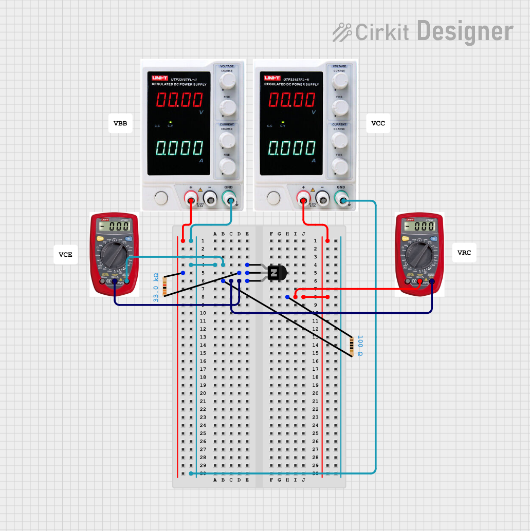 Open Project in Cirkit Designer
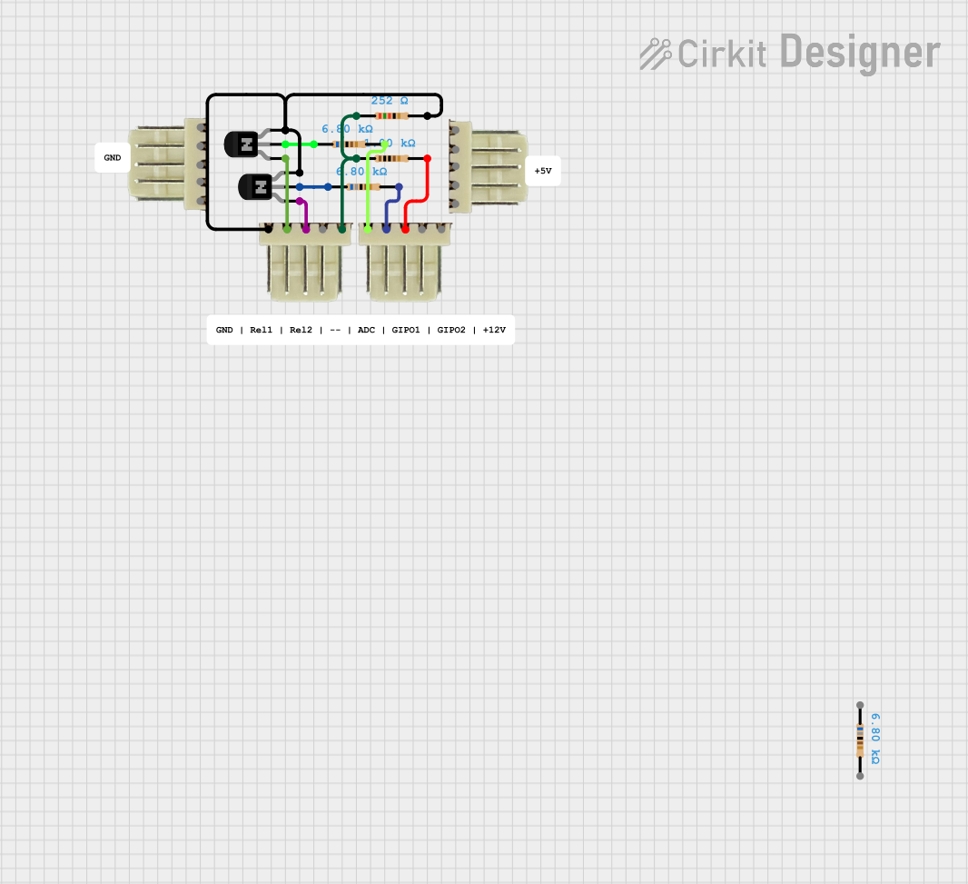 Open Project in Cirkit Designer
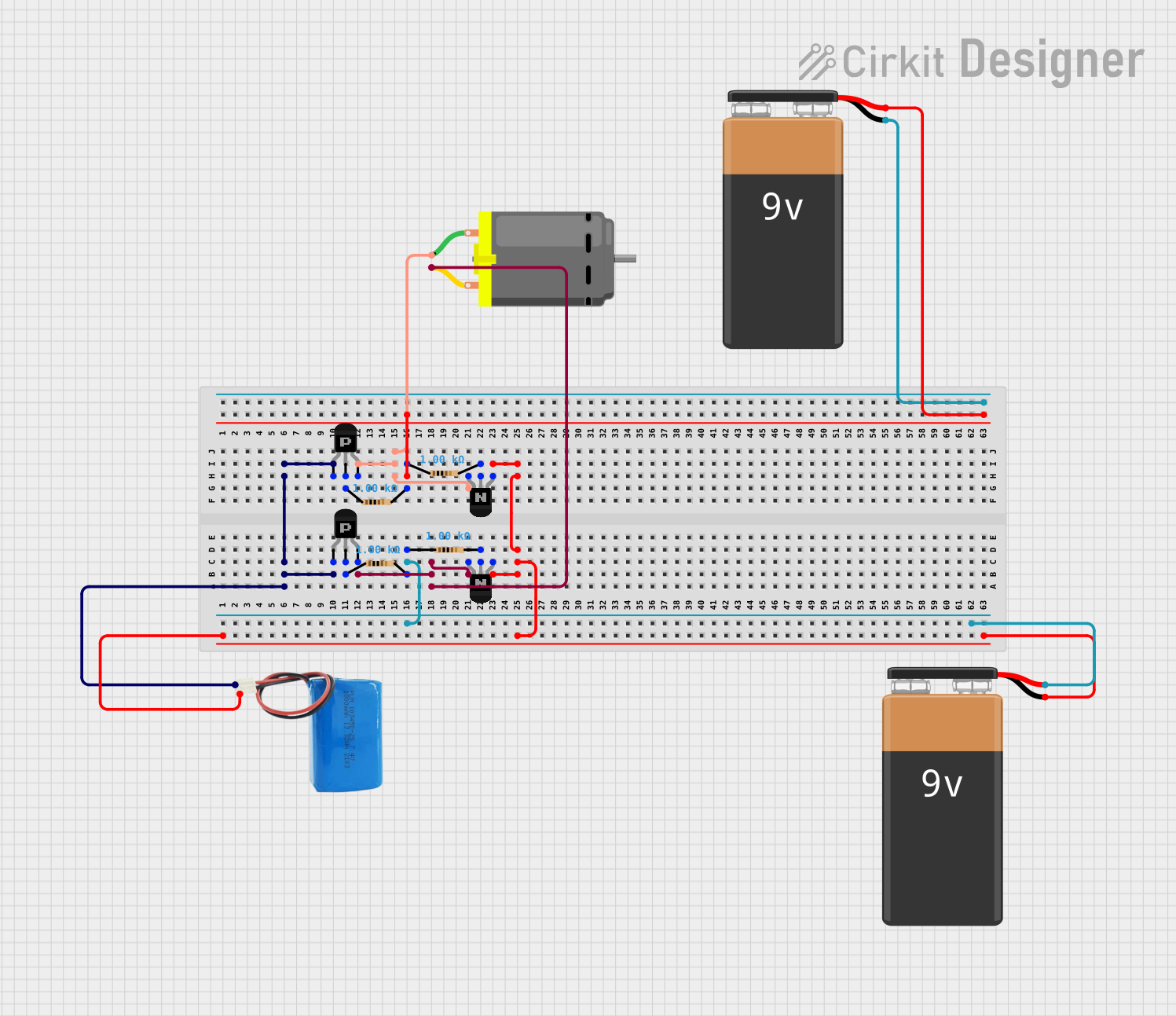 Open Project in Cirkit Designer
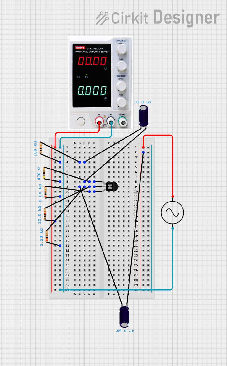 Open Project in Cirkit Designer
Explore Projects Built with TRANSISTOR_NPN
Open Project in Cirkit DesignerOpen Project in Cirkit DesignerOpen Project in Cirkit DesignerOpen Project in Cirkit DesignerTechnical Specifications
Below are the general technical specifications for a standard NPN transistor (e.g., 2N2222 or BC547). Specific values may vary depending on the exact model.
- Type: Bipolar Junction Transistor (BJT)
- Polarity: NPN
- Maximum Collector-Emitter Voltage (VCE): 30V to 60V (varies by model)
- Maximum Collector Current (IC): 100mA to 800mA (varies by model)
- Maximum Power Dissipation (PD): 500mW to 1W
- DC Current Gain (hFE): 100 to 800
- Operating Temperature Range: -55°C to +150°C
Pin Configuration and Descriptions
The NPN transistor typically has three pins: Collector (C), Base (B), and Emitter (E). The pinout may vary depending on the package type (e.g., TO-92, TO-220). Below is the pin configuration for a common TO-92 package.
| Pin Number | Name | Description |
|---|---|---|
| 1 | Collector | The terminal through which the main current flows from the transistor. |
| 2 | Base | The control terminal that regulates the flow of current between collector and emitter. |
| 3 | Emitter | The terminal through which the current exits the transistor. |
Usage Instructions
How to Use the NPN Transistor in a Circuit
- Identify the Pins: Refer to the datasheet or pinout diagram to correctly identify the collector, base, and emitter pins.
- Connect the Circuit:
- Connect the emitter to the ground (negative terminal of the power supply).
- Connect the collector to the load (e.g., a resistor, LED, or motor) and then to the positive terminal of the power supply.
- Apply a small current to the base through a resistor to control the transistor.
- Base Resistor Calculation:
- Use Ohm's Law to calculate the base resistor value:
[
R_B = \frac{V_{in} - V_{BE}}{I_B}
]
Where:
- ( V_{in} ) is the input voltage to the base.
- ( V_{BE} ) is the base-emitter voltage (typically 0.7V for silicon transistors).
- ( I_B ) is the desired base current (usually ( I_C / h_{FE} )).
- Use Ohm's Law to calculate the base resistor value:
[
R_B = \frac{V_{in} - V_{BE}}{I_B}
]
Where:
Example: Controlling an LED with an NPN Transistor and Arduino UNO
Below is an example of how to use an NPN transistor to control an LED with an Arduino UNO.
Circuit Diagram
- Collector: Connect to one terminal of the LED (with a current-limiting resistor in series).
- Emitter: Connect to ground.
- Base: Connect to an Arduino digital pin through a 1kΩ resistor.
Arduino Code
// Define the pin connected to the transistor base
const int transistorBasePin = 9; // Digital pin 9

void setup() {
  pinMode(transistorBasePin, OUTPUT); // Set the pin as an output
}

void loop() {
  digitalWrite(transistorBasePin, HIGH); // Turn on the transistor (LED ON)
  delay(1000); // Wait for 1 second
  digitalWrite(transistorBasePin, LOW);  // Turn off the transistor (LED OFF)
  delay(1000); // Wait for 1 second
}
Important Considerations and Best Practices
- Always use a base resistor to limit the current flowing into the base. Excessive current can damage the transistor.
- Ensure the transistor's maximum voltage and current ratings are not exceeded.
- Use a heat sink if the transistor is dissipating significant power.
- Verify the pinout of the specific transistor model you are using, as it may differ between manufacturers.
Troubleshooting and FAQs
Common Issues
Transistor Not Switching:
- Cause: Insufficient base current or incorrect base resistor value.
- Solution: Recalculate the base resistor value and ensure the base current is sufficient to saturate the transistor.
Overheating:
- Cause: Exceeding the maximum power dissipation or improper heat dissipation.
- Solution: Use a heat sink or reduce the load current.
Incorrect Pin Connections:
- Cause: Misidentification of the collector, base, and emitter pins.
- Solution: Double-check the pinout in the datasheet and ensure proper connections.
LED Not Lighting Up:
- Cause: Incorrect resistor value or insufficient supply voltage.
- Solution: Verify the resistor value and ensure the supply voltage is adequate for the LED and transistor.
FAQs
Q1: Can I use an NPN transistor to control high-power devices?
A1: Yes, but ensure the transistor's current and voltage ratings are sufficient. For high-power applications, consider using a power transistor or a relay.
Q2: What is the difference between an NPN and a PNP transistor?
A2: In an NPN transistor, current flows from the collector to the emitter when the base is supplied with a positive voltage. In a PNP transistor, current flows from the emitter to the collector when the base is supplied with a negative voltage.
Q3: How do I test if an NPN transistor is working?
A3: Use a multimeter in diode mode. Check the base-emitter and base-collector junctions for a forward voltage drop (~0.6-0.7V for silicon transistors). Reverse readings should show no continuity.
By following this documentation, you can effectively use an NPN transistor in your electronic projects!