How to Use Датчик розбиття скла: Examples, Pinouts, and Specs
Introduction
The Датчик розбиття скла (Glass Break Sensor) is a specialized electronic component designed to detect the sound or vibration associated with breaking glass. It is commonly used in security systems to provide an early warning of potential intrusions. By identifying the unique acoustic signature or physical vibrations caused by shattered glass, this sensor can trigger alarms or notifications, enhancing the security of homes, offices, and other facilities.
Explore Projects Built with Датчик розбиття скла


Explore Projects Built with Датчик розбиття скла
Common Applications and Use Cases
- Home and commercial security systems
- Bank and jewelry store protection
- Smart home automation for intrusion detection
- Industrial safety monitoring
- Integration with IoT devices for remote alerts
Technical Specifications
The following table outlines the key technical details of the Датчик розбиття скла:
| Parameter | Value |
|---|---|
| Operating Voltage | 3.3V to 5V |
| Current Consumption | < 20mA |
| Detection Range | Up to 6 meters (20 feet) |
| Detection Angle | 120° |
| Output Signal | Digital (High/Low) |
| Response Time | < 1 second |
| Operating Temperature | -10°C to 50°C |
| Dimensions | 30mm x 20mm x 10mm |
Pin Configuration and Descriptions
The Датчик розбиття скла typically has a 3-pin interface. The pinout is as follows:
| Pin Number | Name | Description |
|---|---|---|
| 1 | VCC | Power supply input (3.3V to 5V) |
| 2 | GND | Ground connection |
| 3 | OUT | Digital output signal (High when glass is broken) |
Usage Instructions
How to Use the Component in a Circuit
- Power the Sensor: Connect the
VCCpin to a 3.3V or 5V power source and theGNDpin to the ground of your circuit. - Connect the Output: Attach the
OUTpin to a microcontroller's digital input pin or directly to an alarm system. - Position the Sensor: Place the sensor within the detection range of the glass you want to monitor. Ensure it is oriented correctly to maximize its detection angle.
- Test the Sensor: Simulate a glass-breaking sound or vibration to verify the sensor's response. The
OUTpin should go HIGH when a break is detected.
Important Considerations and Best Practices
- Avoid False Alarms: Install the sensor in a location where it won't pick up unrelated loud noises or vibrations.
- Power Supply Stability: Use a stable power source to ensure reliable operation.
- Environmental Factors: Avoid placing the sensor in areas with extreme temperatures or high humidity, as these conditions may affect performance.
- Sensitivity Adjustment: Some models may include a sensitivity adjustment feature. Refer to the specific sensor's datasheet for details.
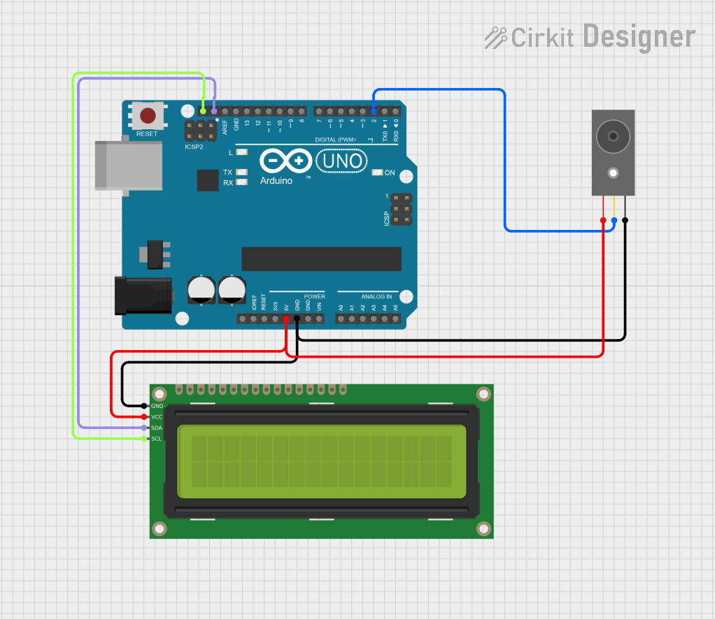
Example: Connecting to an Arduino UNO
Below is an example of how to connect and use the Датчик розбиття скла with an Arduino UNO:
Circuit Connections
- Connect the
VCCpin of the sensor to the 5V pin on the Arduino. - Connect the
GNDpin of the sensor to the GND pin on the Arduino. - Connect the
OUTpin of the sensor to digital pin 2 on the Arduino.
Arduino Code
// Glass Break Sensor Example with Arduino UNO
// This code reads the sensor's output and triggers an alert when glass is broken.

const int sensorPin = 2;  // Pin connected to the sensor's OUT pin
const int ledPin = 13;    // Built-in LED for visual alert

void setup() {
  pinMode(sensorPin, INPUT);  // Set sensor pin as input
  pinMode(ledPin, OUTPUT);    // Set LED pin as output
  Serial.begin(9600);         // Initialize serial communication
}

void loop() {
  int sensorValue = digitalRead(sensorPin);  // Read the sensor's output

  if (sensorValue == HIGH) {
    // Glass break detected
    digitalWrite(ledPin, HIGH);  // Turn on the LED
    Serial.println("Glass break detected!"); // Print alert to serial monitor
    delay(1000);  // Wait for 1 second
  } else {
    // No glass break detected
    digitalWrite(ledPin, LOW);  // Turn off the LED
  }
}
Troubleshooting and FAQs
Common Issues and Solutions
Sensor Not Responding
- Cause: Incorrect wiring or insufficient power supply.
- Solution: Double-check the connections and ensure the power supply matches the sensor's requirements.
False Alarms
- Cause: Environmental noise or vibrations triggering the sensor.
- Solution: Relocate the sensor to a quieter area or adjust its sensitivity (if supported).
No Detection
- Cause: Sensor is out of range or not oriented correctly.
- Solution: Ensure the sensor is within the specified detection range and properly aligned.
Output Signal Stuck HIGH or LOW
- Cause: Faulty sensor or microcontroller pin configuration.
- Solution: Test the sensor with a multimeter or replace it if necessary. Verify the microcontroller's pin settings.
FAQs
Q: Can this sensor detect other types of sounds?
A: No, the sensor is specifically designed to detect the unique sound or vibration of breaking glass.
Q: Is it compatible with 3.3V microcontrollers like ESP32?
A: Yes, the sensor operates within a voltage range of 3.3V to 5V, making it compatible with most microcontrollers.
Q: How do I extend the detection range?
A: The detection range is fixed by the sensor's design. To monitor larger areas, consider using multiple sensors.
Q: Can I use this sensor outdoors?
A: The sensor is not weatherproof. If outdoor use is required, ensure it is housed in a protective enclosure.