
How to Use Serial Adaptor Arduino Module: Examples, Pinouts, and Specs
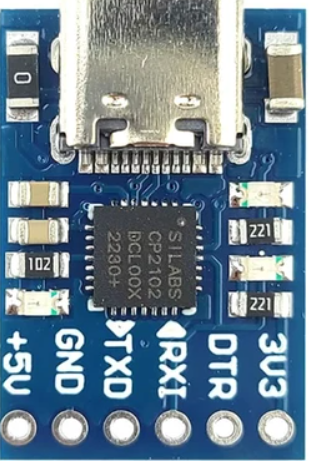
 Design with Serial Adaptor Arduino Module in Cirkit Designer
Introduction
The Serial Adaptor Arduino Module (Manufacturer: EQV, Part ID: CP2102 Micro USB 2.0 UART TTL) is a versatile module designed to facilitate serial communication between an Arduino and other devices. It acts as a bridge, converting USB signals to UART (TTL) signals, enabling seamless data transfer and control. This module is particularly useful for debugging, programming, and interfacing with microcontrollers or other serial devices.
Explore Projects Built with Serial Adaptor Arduino Module
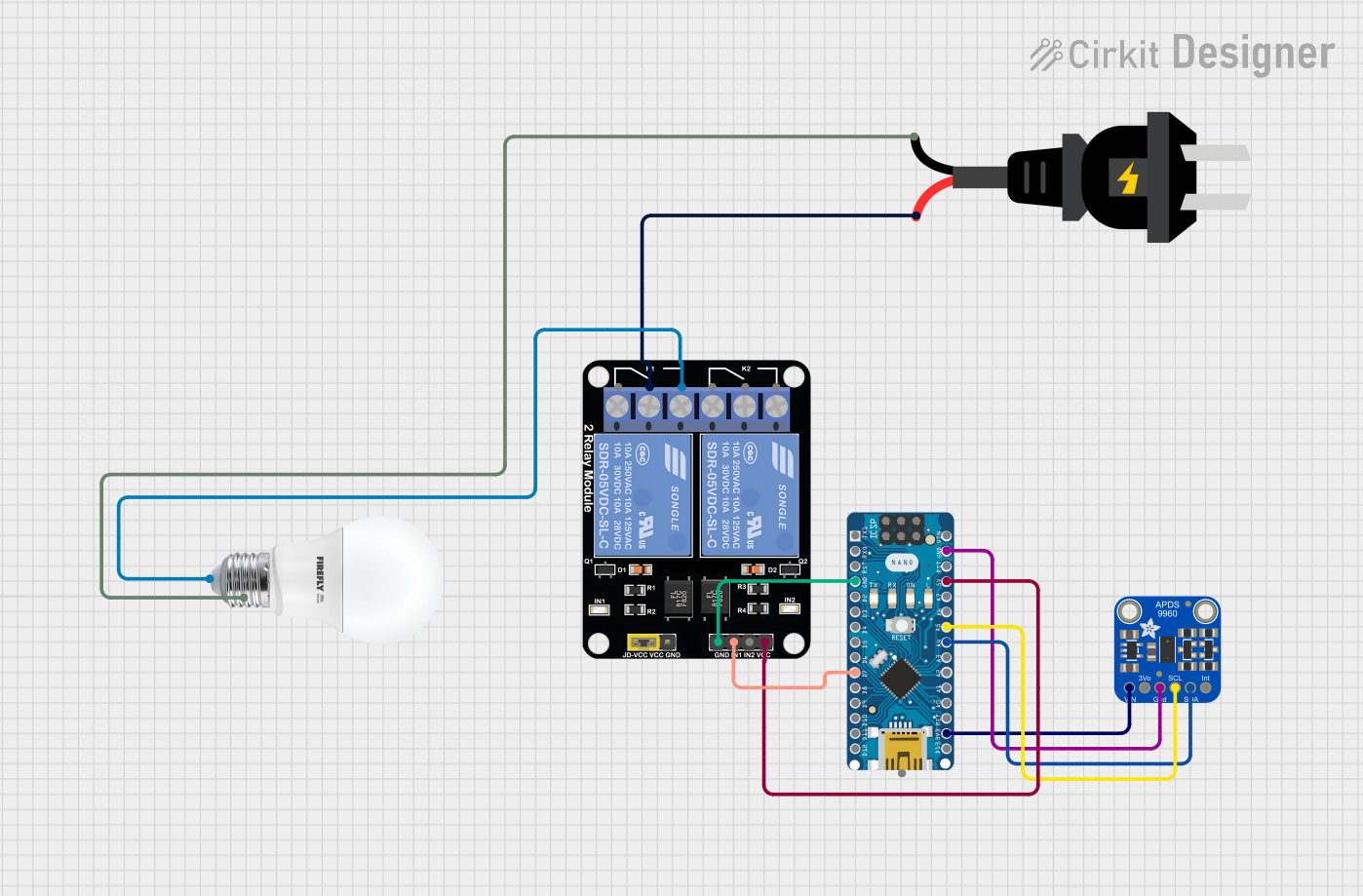 Open Project in Cirkit Designer
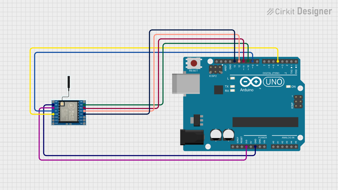 Open Project in Cirkit Designer
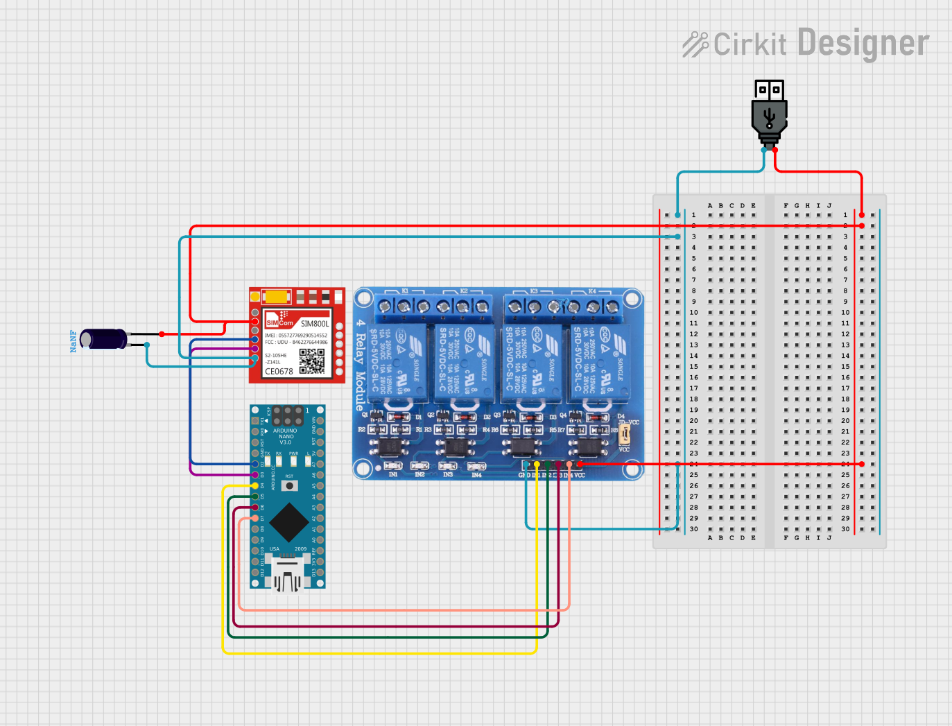 Open Project in Cirkit Designer
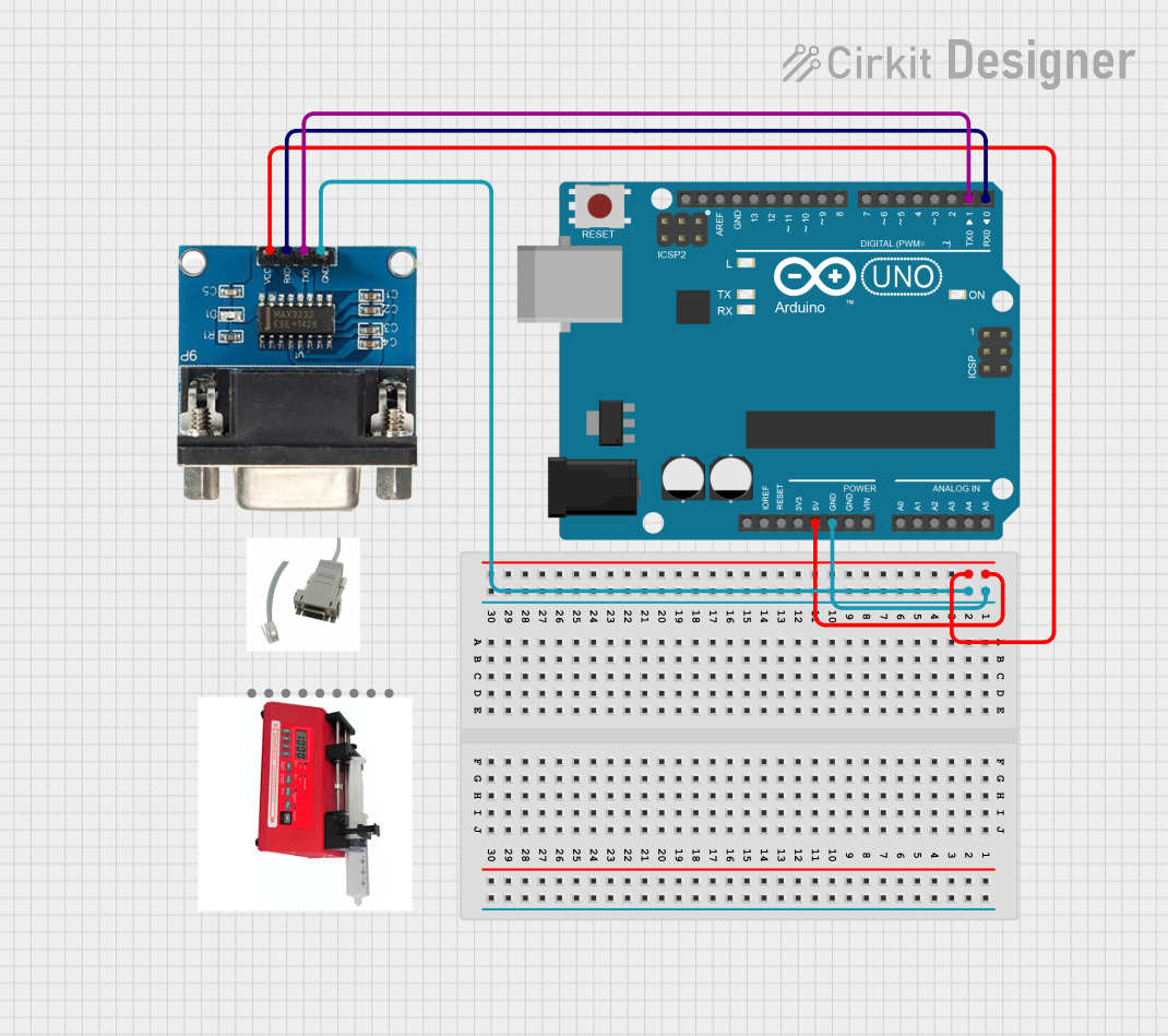 Open Project in Cirkit Designer
Explore Projects Built with Serial Adaptor Arduino Module
Open Project in Cirkit DesignerOpen Project in Cirkit DesignerOpen Project in Cirkit DesignerOpen Project in Cirkit DesignerCommon Applications and Use Cases
- Programming and debugging Arduino boards.
- Interfacing with sensors, modules, or other microcontrollers via UART.
- Serial communication with PCs or laptops for data logging or control.
- Prototyping and testing serial communication protocols.
Technical Specifications
Below are the key technical details of the CP2102 Micro USB 2.0 UART TTL module:
| Specification | Details |
|---|---|
| Manufacturer | EQV |
| Part ID | CP2102 Micro USB 2.0 UART TTL |
| Communication Protocol | USB to UART (TTL) |
| Input Voltage | 5V (via USB) |
| Output Voltage Levels | 3.3V and 5V (selectable via jumper) |
| Baud Rate | 300 bps to 1 Mbps |
| USB Connector Type | Micro USB |
| Operating Temperature | -40°C to +85°C |
| Dimensions | 27mm x 15mm |
| Drivers | Compatible with Windows, macOS, and Linux (drivers may need installation) |
Pin Configuration and Descriptions
The module has a set of pins for interfacing with external devices. Below is the pinout:
| Pin Name | Description |
|---|---|
| TXD | Transmit Data (UART output from the module to the connected device) |
| RXD | Receive Data (UART input to the module from the connected device) |
| GND | Ground (common ground for the module and connected device) |
| VCC | Power output (3.3V or 5V, depending on jumper configuration) |
| DTR | Data Terminal Ready (used for resetting Arduino boards during programming) |
| CTS | Clear to Send (optional, used for hardware flow control in some applications) |
Usage Instructions
How to Use the Module in a Circuit
Connect the Module to Your Computer:
- Use a Micro USB cable to connect the module to your computer. Ensure the appropriate drivers for the CP2102 are installed on your operating system.
Connect to the Arduino or Other Device:
- Connect the TXD pin of the module to the RX pin of the Arduino.
- Connect the RXD pin of the module to the TX pin of the Arduino.
- Connect the GND pin of the module to the GND pin of the Arduino.
- Optionally, connect the DTR pin to the Arduino's RESET pin for automatic resets during programming.
Power the Arduino:
- If the Arduino is not powered separately, you can use the VCC pin of the module to supply power (ensure the correct voltage is selected via the jumper).
Open a Serial Monitor or IDE:
- Use the Arduino IDE or any serial terminal software to communicate with the Arduino or other connected devices.
Important Considerations and Best Practices
- Voltage Selection: Ensure the correct voltage (3.3V or 5V) is selected using the jumper to avoid damaging connected devices.
- Driver Installation: Install the CP2102 drivers from the manufacturer's website if your computer does not recognize the module.
- Baud Rate Matching: Ensure the baud rate in your software matches the baud rate of the connected device.
- Avoid Cross-Connections: Double-check TX and RX connections to prevent communication errors.
Example Code for Arduino UNO
Below is an example of how to use the Serial Adaptor Arduino Module to send and receive data between an Arduino UNO and a computer:
// Example: Serial Communication with CP2102 Module
// This code sends a message to the serial monitor and echoes back received data.

void setup() {
  Serial.begin(9600); // Initialize serial communication at 9600 baud
  while (!Serial) {
    // Wait for the serial connection to be established
    delay(10);
  }
  Serial.println("Serial communication initialized!"); // Send a welcome message
}

void loop() {
  if (Serial.available() > 0) {
    // Check if data is available to read
    char receivedChar = Serial.read(); // Read the incoming character
    Serial.print("You sent: ");        // Print a response
    Serial.println(receivedChar);      // Echo the received character
  }
}
Troubleshooting and FAQs
Common Issues and Solutions
Module Not Recognized by Computer:
- Ensure the CP2102 drivers are installed. Download them from the manufacturer's website.
- Try a different USB cable or port.
No Data Transmission:
- Verify TX and RX connections are correct.
- Check that the baud rate in your software matches the baud rate of the connected device.
Arduino Not Resetting During Programming:
- Ensure the DTR pin is connected to the Arduino's RESET pin.
- Check the jumper settings for proper voltage output.
Data Corruption or Noise:
- Use shorter wires to reduce interference.
- Ensure a common ground connection between the module and the connected device.
FAQs
Q: Can this module power my Arduino?
A: Yes, the module can supply 3.3V or 5V to the Arduino via the VCC pin, but ensure the jumper is set to the correct voltage.
Q: Is this module compatible with all Arduino boards?
A: Yes, it is compatible with most Arduino boards that support UART communication, including the Arduino UNO, Nano, and Mega.
Q: Do I need to install drivers on Linux?
A: Most Linux distributions include built-in support for the CP2102 module. However, if it is not recognized, you may need to install additional drivers.
Q: Can I use this module for other microcontrollers?
A: Yes, the module can interface with any device that supports UART communication, such as ESP8266, ESP32, or Raspberry Pi.
By following this documentation, you can effectively use the Serial Adaptor Arduino Module for your projects and troubleshoot common issues with ease.