
How to Use Terminal PCB 2 Pin: Examples, Pinouts, and Specs
 Design with Terminal PCB 2 Pin in Cirkit Designer
Introduction
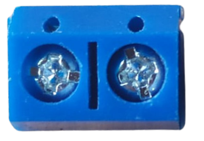
The Terminal PCB 2 Pin is a compact and reliable two-pin terminal block designed for printed circuit boards (PCBs). It provides a convenient way to connect and disconnect wires in electronic circuits without the need for soldering. This component is widely used in applications where secure and removable wire connections are required, such as power supplies, control systems, and prototyping.
Explore Projects Built with Terminal PCB 2 Pin
 Open Project in Cirkit Designer
 Open Project in Cirkit Designer
 Open Project in Cirkit Designer
 Open Project in Cirkit Designer
Explore Projects Built with Terminal PCB 2 Pin
Open Project in Cirkit DesignerOpen Project in Cirkit DesignerOpen Project in Cirkit DesignerOpen Project in Cirkit DesignerCommon Applications and Use Cases
- Power supply connections in electronic devices
- Signal connections in control systems
- Prototyping and testing circuits
- Industrial automation and robotics
- Audio and speaker connections
Technical Specifications
The following table outlines the key technical details of the Terminal PCB 2 Pin:
| Parameter | Specification |
|---|---|
| Number of Pins | 2 |
| Rated Voltage | 300V |
| Rated Current | 10A |
| Wire Gauge Support | 26-12 AWG |
| Pitch (Pin Spacing) | 5.08 mm (0.2 inches) |
| Material | Flame-retardant thermoplastic (UL94V-0) |
| Contact Material | Copper alloy with nickel or tin plating |
| Operating Temperature | -40°C to +105°C |
Pin Configuration and Descriptions
The Terminal PCB 2 Pin has two pins for electrical connections and two screw terminals for securing wires. The pin configuration is as follows:
| Pin Number | Description |
|---|---|
| 1 | Positive terminal (V+) |
| 2 | Negative terminal (V-) |
Usage Instructions
How to Use the Terminal PCB 2 Pin in a Circuit
- Mounting on PCB: Solder the two pins of the terminal block onto the PCB at the designated location. Ensure proper alignment with the PCB layout.
- Connecting Wires:
- Strip the insulation from the wire ends (approximately 5-7 mm).
- Insert the stripped wire ends into the screw terminals.
- Tighten the screws securely to hold the wires in place.
- Testing the Connection: Verify the connection by gently tugging on the wires to ensure they are firmly secured.
Important Considerations and Best Practices
- Wire Gauge Compatibility: Ensure the wires used are within the supported range (26-12 AWG) for optimal connection.
- Tightening Screws: Avoid overtightening the screws, as this may damage the wire or the terminal block.
- PCB Design: When designing the PCB, ensure the pin spacing (5.08 mm) matches the terminal block's pitch.
- Current and Voltage Ratings: Do not exceed the rated current (10A) or voltage (300V) to prevent overheating or damage.
- Environmental Conditions: Use the terminal block within the specified operating temperature range (-40°C to +105°C).
Example: Connecting to an Arduino UNO
The Terminal PCB 2 Pin can be used to connect external components, such as a power supply or motor, to an Arduino UNO. Below is an example of connecting a 12V DC motor to an Arduino using the terminal block:
Circuit Diagram
- Connect the positive terminal of the motor to the V+ pin of the terminal block.
- Connect the negative terminal of the motor to the V- pin of the terminal block.
- Use a motor driver (e.g., L298N) to interface the motor with the Arduino.
Arduino Code Example
// Example code to control a DC motor using Arduino and a motor driver

const int motorPin1 = 9; // Pin connected to motor driver input 1
const int motorPin2 = 10; // Pin connected to motor driver input 2

void setup() {
  pinMode(motorPin1, OUTPUT); // Set motorPin1 as output
  pinMode(motorPin2, OUTPUT); // Set motorPin2 as output
}

void loop() {
  // Rotate motor in one direction
  digitalWrite(motorPin1, HIGH); // Set motorPin1 HIGH
  digitalWrite(motorPin2, LOW);  // Set motorPin2 LOW
  delay(2000); // Run motor for 2 seconds

  // Stop the motor
  digitalWrite(motorPin1, LOW);  // Set motorPin1 LOW
  digitalWrite(motorPin2, LOW);  // Set motorPin2 LOW
  delay(1000); // Pause for 1 second

  // Rotate motor in the opposite direction
  digitalWrite(motorPin1, LOW);  // Set motorPin1 LOW
  digitalWrite(motorPin2, HIGH); // Set motorPin2 HIGH
  delay(2000); // Run motor for 2 seconds

  // Stop the motor
  digitalWrite(motorPin1, LOW);  // Set motorPin1 LOW
  digitalWrite(motorPin2, LOW);  // Set motorPin2 LOW
  delay(1000); // Pause for 1 second
}
Troubleshooting and FAQs
Common Issues and Solutions
Loose Wire Connections:
- Issue: Wires are not securely held in the terminal block.
- Solution: Ensure the screws are tightened properly and the wire ends are stripped to the correct length.
Overheating:
- Issue: The terminal block becomes hot during operation.
- Solution: Check that the current and voltage do not exceed the rated limits (10A, 300V).
Misalignment on PCB:
- Issue: The terminal block does not fit properly on the PCB.
- Solution: Verify that the PCB layout matches the terminal block's pin spacing (5.08 mm).
Corrosion or Poor Contact:
- Issue: Electrical contact is unreliable due to corrosion.
- Solution: Use terminal blocks with tin or nickel plating and ensure the environment is dry and clean.
FAQs
Q1: Can I use the Terminal PCB 2 Pin for AC connections?
A1: Yes, the terminal block can handle AC connections as long as the voltage and current ratings (300V, 10A) are not exceeded.
Q2: Is the Terminal PCB 2 Pin reusable?
A2: Yes, the terminal block is reusable. You can disconnect and reconnect wires multiple times without degrading its performance.
Q3: What tools are required to use this component?
A3: You will need a screwdriver to tighten the screws and a wire stripper to prepare the wire ends.
Q4: Can I use this terminal block for high-frequency signals?
A4: While it can handle low-frequency signals, it is not recommended for high-frequency applications due to potential signal degradation.