Cirkit Designer Logo
Cirkit Designer
Your all-in-one circuit design IDE
Home / 
Component Documentation

How to Use POWER SUPPLY 12V 5AMP: Examples, Pinouts, and Specs

Image of POWER SUPPLY 12V 5AMP
Cirkit Designer LogoDesign with POWER SUPPLY 12V 5AMP in Cirkit Designer

Introduction

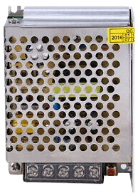
The POWER SUPPLY 12V 5AMP is a device designed to convert electrical energy from an input source (such as an AC mains supply) into a stable 12V DC output. It is capable of delivering up to 5 amps of current, making it suitable for powering a wide range of electronic circuits and devices. This power supply is commonly used in applications requiring a reliable and consistent 12V power source, such as LED lighting systems, motor drivers, microcontroller-based projects, and other electronic equipment.

Explore Projects Built with POWER SUPPLY 12V 5AMP

Use Cirkit Designer to design, explore, and prototype these projects online. Some projects support real-time simulation. Click "Open Project" to start designing instantly!
Dual 5V Power Supply Distribution Circuit with Toggle Switch Control
Image of rfdriver: A project utilizing POWER SUPPLY 12V 5AMP in a practical application
This circuit consists of two 5V 5A power supplies connected to an AC wall plug point, providing DC output through a 12-way connector. The ground connections from both power supplies are interconnected and also connected to the ground pins of two toggle switches. The DC outputs from the power supplies are separately connected to different pins on the 12-way connector, with each power supply output being switchable via one of the toggle switches.
Cirkit Designer LogoOpen Project in Cirkit Designer
12V to 5V Power Supply with LED Indicator and Push Switch
Image of Power Supply LVCO: A project utilizing POWER SUPPLY 12V 5AMP in a practical application
This circuit is a 12V to 5V regulated power supply with an LED indicator. It uses a 5408 diode for reverse polarity protection, an LM340T5 7805 voltage regulator to step down the voltage to 5V, and a push switch to control the LED indicator. The circuit also includes capacitors for filtering and a resistor to limit the current through the LED.
Cirkit Designer LogoOpen Project in Cirkit Designer
12V UPS System with Dual 18650 Li-ion Battery Backup and Voltage Regulation
Image of Power supply: A project utilizing POWER SUPPLY 12V 5AMP in a practical application
This circuit is designed to provide an uninterruptible power supply (UPS) system with a 12V DC output. It includes a 12V 5A power supply connected to an AC source through a toggle switch, which charges a pair of 18650 Li-ion batteries via a voltage regulator (XL4016). The UPS module ensures a continuous power supply to the load by switching between the power supply and the battery bank.
Cirkit Designer LogoOpen Project in Cirkit Designer
12V Multi-Component Control Circuit
Image of DEWX MOTOR 2: A project utilizing POWER SUPPLY 12V 5AMP in a practical application
This circuit appears to be a power distribution system that supplies power to various components from a 12V 5A power supply. It connects the negative terminal of the power supply to the ground (GND) pins of a mini diaphragm water pump, an RGB LED, a fan, and a water pump, while the positive DC output is connected to the positive pins of the RGB LED and presumably to other components through JST PH 2.0 connectors. The circuit lacks a controlling element, such as a microcontroller, suggesting that the components operate continuously or are switched externally.
Cirkit Designer LogoOpen Project in Cirkit Designer

Explore Projects Built with POWER SUPPLY 12V 5AMP

Use Cirkit Designer to design, explore, and prototype these projects online. Some projects support real-time simulation. Click "Open Project" to start designing instantly!
Image of rfdriver: A project utilizing POWER SUPPLY 12V 5AMP in a practical application
Dual 5V Power Supply Distribution Circuit with Toggle Switch Control
This circuit consists of two 5V 5A power supplies connected to an AC wall plug point, providing DC output through a 12-way connector. The ground connections from both power supplies are interconnected and also connected to the ground pins of two toggle switches. The DC outputs from the power supplies are separately connected to different pins on the 12-way connector, with each power supply output being switchable via one of the toggle switches.
Cirkit Designer LogoOpen Project in Cirkit Designer
Image of Power Supply LVCO: A project utilizing POWER SUPPLY 12V 5AMP in a practical application
12V to 5V Power Supply with LED Indicator and Push Switch
This circuit is a 12V to 5V regulated power supply with an LED indicator. It uses a 5408 diode for reverse polarity protection, an LM340T5 7805 voltage regulator to step down the voltage to 5V, and a push switch to control the LED indicator. The circuit also includes capacitors for filtering and a resistor to limit the current through the LED.
Cirkit Designer LogoOpen Project in Cirkit Designer
Image of Power supply: A project utilizing POWER SUPPLY 12V 5AMP in a practical application
12V UPS System with Dual 18650 Li-ion Battery Backup and Voltage Regulation
This circuit is designed to provide an uninterruptible power supply (UPS) system with a 12V DC output. It includes a 12V 5A power supply connected to an AC source through a toggle switch, which charges a pair of 18650 Li-ion batteries via a voltage regulator (XL4016). The UPS module ensures a continuous power supply to the load by switching between the power supply and the battery bank.
Cirkit Designer LogoOpen Project in Cirkit Designer
Image of DEWX MOTOR 2: A project utilizing POWER SUPPLY 12V 5AMP in a practical application
12V Multi-Component Control Circuit
This circuit appears to be a power distribution system that supplies power to various components from a 12V 5A power supply. It connects the negative terminal of the power supply to the ground (GND) pins of a mini diaphragm water pump, an RGB LED, a fan, and a water pump, while the positive DC output is connected to the positive pins of the RGB LED and presumably to other components through JST PH 2.0 connectors. The circuit lacks a controlling element, such as a microcontroller, suggesting that the components operate continuously or are switched externally.
Cirkit Designer LogoOpen Project in Cirkit Designer

Common Applications and Use Cases

  • Powering microcontroller boards (e.g., Arduino, Raspberry Pi) and their peripherals
  • Driving LED strips, modules, or lighting systems
  • Supplying power to DC motors and motor drivers
  • Providing a stable power source for audio amplifiers
  • General-purpose use in prototyping and testing electronic circuits

Technical Specifications

Below are the key technical details and pin configuration of the POWER SUPPLY 12V 5AMP:

Key Technical Details

Parameter Specification
Input Voltage Range 100-240V AC, 50/60Hz
Output Voltage 12V DC
Maximum Output Current 5A
Power Output 60W
Efficiency ≥85%
Ripple and Noise ≤120mVp-p
Operating Temperature -10°C to +50°C
Protection Features Overload, Overvoltage, Short Circuit

Pin Configuration and Descriptions

Pin Name Description
AC Input (L) Live wire connection for AC mains input
AC Input (N) Neutral wire connection for AC mains input
Ground (GND) Earth/ground connection for safety
DC Output (+) Positive 12V DC output terminal
DC Output (-) Negative (ground) DC output terminal

Usage Instructions

How to Use the Component in a Circuit

  1. Connect the AC Input:

    • Ensure the power supply is disconnected from the mains before wiring.
    • Connect the live (L) and neutral (N) wires of the AC mains to the respective input terminals of the power supply.
    • Optionally, connect the ground (GND) terminal to the earth wire for safety.
  2. Connect the DC Output:

    • Identify the positive (+) and negative (-) output terminals.
    • Connect the positive terminal to the positive rail of your circuit and the negative terminal to the ground rail.
  3. Power On:

    • After verifying all connections, plug the power supply into the mains and switch it on.
    • Use a multimeter to confirm the output voltage is 12V before connecting sensitive devices.

Important Considerations and Best Practices

  • Load Requirements: Ensure the total current draw of connected devices does not exceed 5A.
  • Ventilation: Place the power supply in a well-ventilated area to prevent overheating.
  • Polarity: Double-check the polarity of the DC output connections to avoid damaging your circuit.
  • Safety: Always disconnect the power supply from the mains before making any wiring changes.

Example: Using with an Arduino UNO

The POWER SUPPLY 12V 5AMP can be used to power an Arduino UNO via its barrel jack or VIN pin. Below is an example of how to connect and use it:

  1. Connect the positive (+) output of the power supply to the Arduino's VIN pin or barrel jack center pin.
  2. Connect the negative (-) output of the power supply to the Arduino's GND pin or barrel jack outer sleeve.
  3. Ensure the Arduino's onboard voltage regulator is functioning properly to step down the 12V to 5V for internal use.

Sample Arduino Code

// Example: Blinking an LED using Arduino UNO powered by a 12V 5A power supply

const int ledPin = 13; // Pin connected to the onboard LED

void setup() {
  pinMode(ledPin, OUTPUT); // Set the LED pin as an output
}

void loop() {
  digitalWrite(ledPin, HIGH); // Turn the LED on
  delay(1000); // Wait for 1 second
  digitalWrite(ledPin, LOW); // Turn the LED off
  delay(1000); // Wait for 1 second
}

Note: Ensure the Arduino UNO is not drawing more than its rated current. The onboard regulator will handle the 12V input.


Troubleshooting and FAQs

Common Issues and Solutions

Issue Possible Cause Solution
No output voltage Loose or incorrect AC input connection Verify and secure the AC input connections
Output voltage is not 12V Overload or faulty power supply Reduce the load or replace the power supply
Power supply overheats Poor ventilation or excessive load Ensure proper airflow and reduce the load
Devices not powering on Incorrect polarity or loose connections Check and correct the polarity and wiring

FAQs

  1. Can I use this power supply for devices requiring less than 5A?

    • Yes, the power supply will only deliver the current required by the connected device, up to a maximum of 5A.
  2. Is this power supply suitable for outdoor use?

    • No, this power supply is designed for indoor use. Use a weatherproof enclosure if outdoor operation is required.
  3. What happens if I connect a device that requires more than 5A?

    • The power supply's overload protection will activate, shutting down the output to prevent damage.
  4. Can I use this power supply with a battery charger circuit?

    • Yes, as long as the charger circuit is designed to operate with a 12V DC input.

This documentation provides all the necessary details to effectively use and troubleshoot the POWER SUPPLY 12V 5AMP. Always follow safety guidelines when working with electrical components.