How to Use LD2410C: Examples, Pinouts, and Specs
Introduction
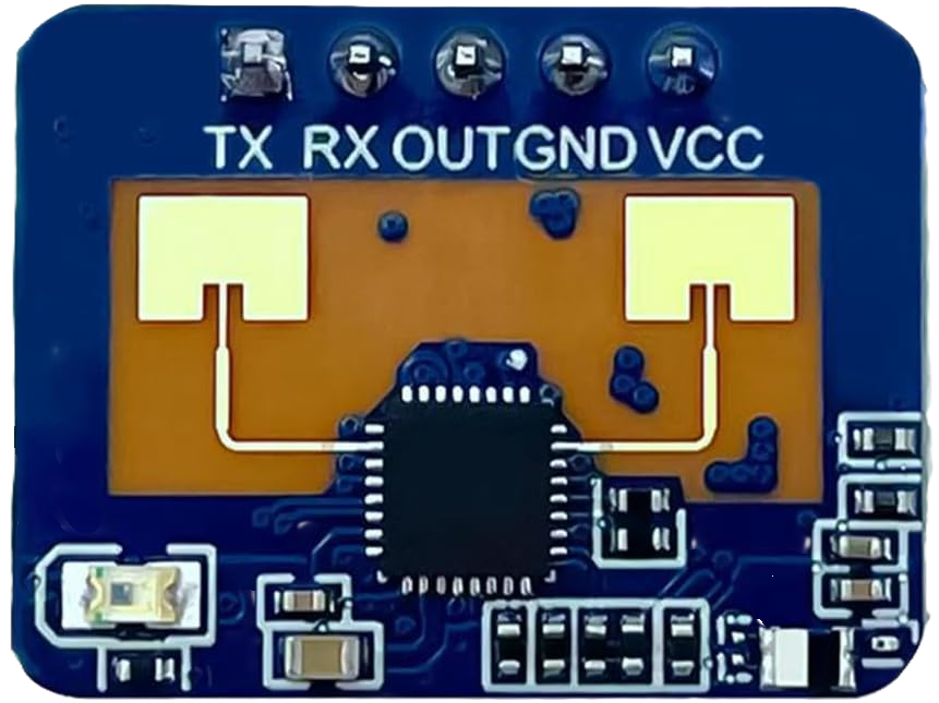
The LD2410C (manufacturer part ID: HLK-LD2410C) is a low-power, high-performance microwave motion detector IC developed by Hi-Link. Operating in the 24 GHz frequency range, this component is designed for motion detection in security, automation, and smart home applications. It features a built-in antenna, simplifying integration into various systems and reducing the need for external RF components.
Explore Projects Built with LD2410C


Explore Projects Built with LD2410C
Common Applications
- Security systems (e.g., motion-activated alarms)
- Smart lighting and home automation
- Occupancy detection in offices and buildings
- Industrial automation and robotics
- Energy-saving systems (e.g., HVAC control)
Technical Specifications
Key Technical Details
| Parameter | Value |
|---|---|
| Operating Frequency | 24 GHz |
| Operating Voltage | 5V DC |
| Operating Current | ≤ 50 mA |
| Detection Range | 0.5 m to 10 m (adjustable) |
| Detection Angle | 120° (horizontal) |
| Communication Interface | UART |
| Operating Temperature | -40°C to +85°C |
| Dimensions | 33 mm x 20 mm x 8 mm |
Pin Configuration and Descriptions
The LD2410C module has a simple pinout for easy integration into circuits. Below is the pin configuration:
| Pin Number | Pin Name | Description |
|---|---|---|
| 1 | VCC | Power supply input (5V DC) |
| 2 | GND | Ground connection |
| 3 | TX | UART transmit pin (data output) |
| 4 | RX | UART receive pin (data input) |
| 5 | EN | Enable pin (active high, optional) |
Usage Instructions
How to Use the LD2410C in a Circuit
- Power Supply: Connect the VCC pin to a stable 5V DC power source and the GND pin to ground.
- UART Communication: Use the TX and RX pins to interface with a microcontroller or computer for data communication. Ensure the UART baud rate matches the module's default setting (115200 bps).
- Enable Pin: Optionally, connect the EN pin to a GPIO pin on your microcontroller to enable or disable the module programmatically.
- Detection Range Adjustment: The detection range can be configured via UART commands. Refer to the manufacturer's protocol documentation for details.
Important Considerations and Best Practices
- Placement: Install the LD2410C in a location free from obstructions to maximize detection accuracy.
- Power Supply: Use a regulated 5V power source to avoid voltage fluctuations that could affect performance.
- Interference: Avoid placing the module near other high-frequency devices to minimize interference.
- UART Configuration: Ensure the microcontroller's UART settings (baud rate, parity, etc.) match the LD2410C's default configuration.
Example: Connecting LD2410C to an Arduino UNO
Below is an example of how to connect and use the LD2410C with an Arduino UNO:
Wiring Diagram
| LD2410C Pin | Arduino UNO Pin |
|---|---|
| VCC | 5V |
| GND | GND |
| TX | D2 (via voltage divider if needed) |
| RX | D3 |
Arduino Code
#include <SoftwareSerial.h>

// Define RX and TX pins for SoftwareSerial
SoftwareSerial ld2410Serial(2, 3); // RX = Pin 2, TX = Pin 3

void setup() {
  Serial.begin(9600); // Initialize Serial Monitor
  ld2410Serial.begin(115200); // Initialize LD2410C UART communication

  Serial.println("LD2410C Motion Detector Initialized");
}

void loop() {
  // Check if data is available from the LD2410C
  if (ld2410Serial.available()) {
    String data = "";
    while (ld2410Serial.available()) {
      char c = ld2410Serial.read();
      data += c; // Read incoming data
    }
    Serial.println("Motion Data: " + data); // Print data to Serial Monitor
  }

  delay(100); // Small delay to avoid flooding the Serial Monitor
}
Note: If the LD2410C's TX pin outputs 5V logic, no voltage divider is needed. If it outputs 3.3V logic, ensure the Arduino UNO can read 3.3V signals reliably.
Troubleshooting and FAQs
Common Issues and Solutions
No Motion Detected:
- Ensure the module is powered correctly (check VCC and GND connections).
- Verify the detection range settings via UART commands.
- Check for obstructions in the detection area.
UART Communication Fails:
- Confirm the baud rate is set to 115200 bps on both the LD2410C and the microcontroller.
- Check the wiring of the TX and RX pins. Ensure they are not swapped.
- Use a logic level converter if interfacing with a 3.3V microcontroller.
Interference or False Triggers:
- Relocate the module away from other RF-emitting devices.
- Reduce the detection range to minimize environmental noise.
FAQs
Q: Can the detection range be adjusted?
A: Yes, the detection range can be configured via UART commands. Refer to the manufacturer's protocol for details.
Q: Is the LD2410C suitable for outdoor use?
A: The module operates in a wide temperature range (-40°C to +85°C), but it is not waterproof. Use a protective enclosure for outdoor applications.
Q: What is the default UART baud rate?
A: The default UART baud rate is 115200 bps.
Q: Can the LD2410C detect stationary objects?
A: No, the LD2410C is designed for motion detection and cannot detect stationary objects.
Q: Does the module require an external antenna?
A: No, the LD2410C has a built-in antenna, simplifying integration into your project.