How to Use Motor Driver: Examples, Pinouts, and Specs
Introduction
A motor driver is an electronic circuit that controls the operation of a motor by providing the necessary voltage and current, allowing for direction and speed control. The DfRobot motor driver is a versatile and reliable component designed to interface with various types of DC motors, stepper motors, and servo motors. It is widely used in robotics, automation systems, and other motor-driven applications.
Explore Projects Built with Motor Driver


Explore Projects Built with Motor Driver
Common Applications and Use Cases
- Robotics: Controlling the movement of robot wheels or arms.
- Automation: Driving conveyor belts or automated systems.
- DIY Projects: Building motorized toys or gadgets.
- Industrial Systems: Operating motors in manufacturing or assembly lines.
Technical Specifications
The DfRobot motor driver is designed to handle a wide range of motors and offers robust performance. Below are the key technical details:
General Specifications
- Operating Voltage: 6V to 12V
- Maximum Output Current: 2A per channel
- Number of Channels: 2 (can control two motors simultaneously)
- Control Logic Voltage: 3.3V to 5V (compatible with most microcontrollers)
- PWM Frequency: Up to 20 kHz
- Motor Types Supported: DC motors, stepper motors, and servo motors
- Built-in Protection: Overcurrent and thermal shutdown
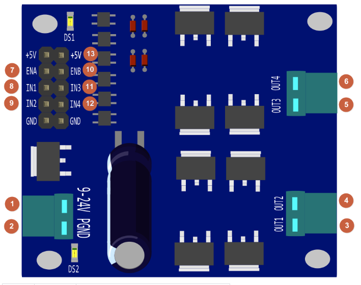
Pin Configuration and Descriptions
The DfRobot motor driver typically comes with a set of pins for control and power connections. Below is the pin configuration:
| Pin Name | Description |
|---|---|
| VCC | Power supply for the motor driver (6V to 12V). |
| GND | Ground connection. |
| IN1 | Input signal for controlling Motor 1 direction (logic HIGH or LOW). |
| IN2 | Input signal for controlling Motor 1 direction (logic HIGH or LOW). |
| IN3 | Input signal for controlling Motor 2 direction (logic HIGH or LOW). |
| IN4 | Input signal for controlling Motor 2 direction (logic HIGH or LOW). |
| ENA | PWM input for speed control of Motor 1. |
| ENB | PWM input for speed control of Motor 2. |
| OUT1 | Output terminal for Motor 1 connection. |
| OUT2 | Output terminal for Motor 1 connection. |
| OUT3 | Output terminal for Motor 2 connection. |
| OUT4 | Output terminal for Motor 2 connection. |
Usage Instructions
How to Use the Component in a Circuit
- Power Supply: Connect the VCC pin to a power source (6V to 12V) and the GND pin to the ground.
- Motor Connections: Connect the motor terminals to the OUT1/OUT2 pins (for Motor 1) or OUT3/OUT4 pins (for Motor 2).
- Control Signals: Use IN1 and IN2 to control the direction of Motor 1, and IN3 and IN4 for Motor 2. Apply a HIGH or LOW signal to these pins based on the desired direction.
- Speed Control: Connect the ENA and ENB pins to PWM outputs of a microcontroller to control the speed of Motor 1 and Motor 2, respectively.
Important Considerations and Best Practices
- Ensure the power supply voltage matches the motor's operating voltage to avoid damage.
- Use appropriate heat sinks or cooling mechanisms if the motor driver operates at high currents for extended periods.
- Avoid reversing the polarity of the power supply or motor connections.
- Use decoupling capacitors near the power supply pins to reduce noise and improve stability.
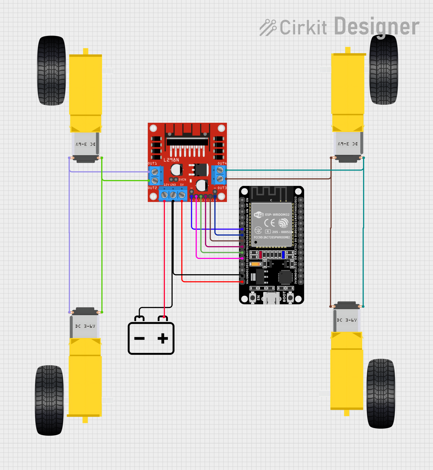
Example: Connecting to an Arduino UNO
Below is an example of how to control two DC motors using the DfRobot motor driver and an Arduino UNO:
// Define motor control pins
const int IN1 = 7;  // Motor 1 direction control pin
const int IN2 = 6;  // Motor 1 direction control pin
const int ENA = 5;  // Motor 1 speed control (PWM) pin
const int IN3 = 4;  // Motor 2 direction control pin
const int IN4 = 3;  // Motor 2 direction control pin
const int ENB = 2;  // Motor 2 speed control (PWM) pin

void setup() {
  // Set motor control pins as outputs
  pinMode(IN1, OUTPUT);
  pinMode(IN2, OUTPUT);
  pinMode(ENA, OUTPUT);
  pinMode(IN3, OUTPUT);
  pinMode(IN4, OUTPUT);
  pinMode(ENB, OUTPUT);
}

void loop() {
  // Motor 1: Forward at 50% speed
  digitalWrite(IN1, HIGH);  // Set direction
  digitalWrite(IN2, LOW);
  analogWrite(ENA, 128);    // Set speed (0-255)

  // Motor 2: Backward at 75% speed
  digitalWrite(IN3, LOW);   // Set direction
  digitalWrite(IN4, HIGH);
  analogWrite(ENB, 192);    // Set speed (0-255)

  delay(2000);              // Run motors for 2 seconds

  // Stop both motors
  analogWrite(ENA, 0);
  analogWrite(ENB, 0);

  delay(2000);              // Wait for 2 seconds
}
Troubleshooting and FAQs
Common Issues and Solutions
Motors Not Running:
- Cause: Incorrect wiring or loose connections.
- Solution: Double-check all connections, especially the motor and power supply pins.
Motor Driver Overheating:
- Cause: Excessive current draw or insufficient cooling.
- Solution: Ensure the motor's current rating is within the driver's limits. Add a heat sink or cooling fan if necessary.
Erratic Motor Behavior:
- Cause: Noise or interference in the control signals.
- Solution: Use decoupling capacitors near the power supply and keep control signal wires short.
PWM Speed Control Not Working:
- Cause: Incorrect PWM signal or incompatible microcontroller.
- Solution: Verify the PWM frequency and duty cycle. Ensure the microcontroller's logic voltage matches the motor driver's requirements.
FAQs
Q: Can I use this motor driver with a 24V motor?
A: No, the maximum operating voltage is 12V. Using a higher voltage may damage the driver.Q: How many motors can this driver control?
A: The DfRobot motor driver can control up to two DC motors or one stepper motor.Q: Is it compatible with Raspberry Pi?
A: Yes, as long as the control logic voltage (3.3V) is within the driver's supported range.Q: Can I use this driver for brushless motors?
A: No, this driver is designed for brushed DC motors, stepper motors, and servo motors. Brushless motors require a specialized driver.