
How to Use Adafruit DRV2605L Haptic Motor Controller - STEMMA QT: Examples, Pinouts, and Specs
 Design with Adafruit DRV2605L Haptic Motor Controller - STEMMA QT in Cirkit Designer
Introduction
The Adafruit DRV2605L Haptic Motor Controller (Part ID: 2305) is a compact and versatile module designed to control vibration motors with precision. It enables the creation of tactile feedback in devices, making it ideal for applications requiring haptic feedback, such as wearables, gaming controllers, and user interfaces. The controller supports a wide range of haptic effects and features an I²C interface for easy communication. Additionally, the inclusion of STEMMA QT connectors simplifies integration into projects, especially for prototyping and development.
Explore Projects Built with Adafruit DRV2605L Haptic Motor Controller - STEMMA QT
 Open Project in Cirkit Designer
 Open Project in Cirkit Designer
 Open Project in Cirkit Designer
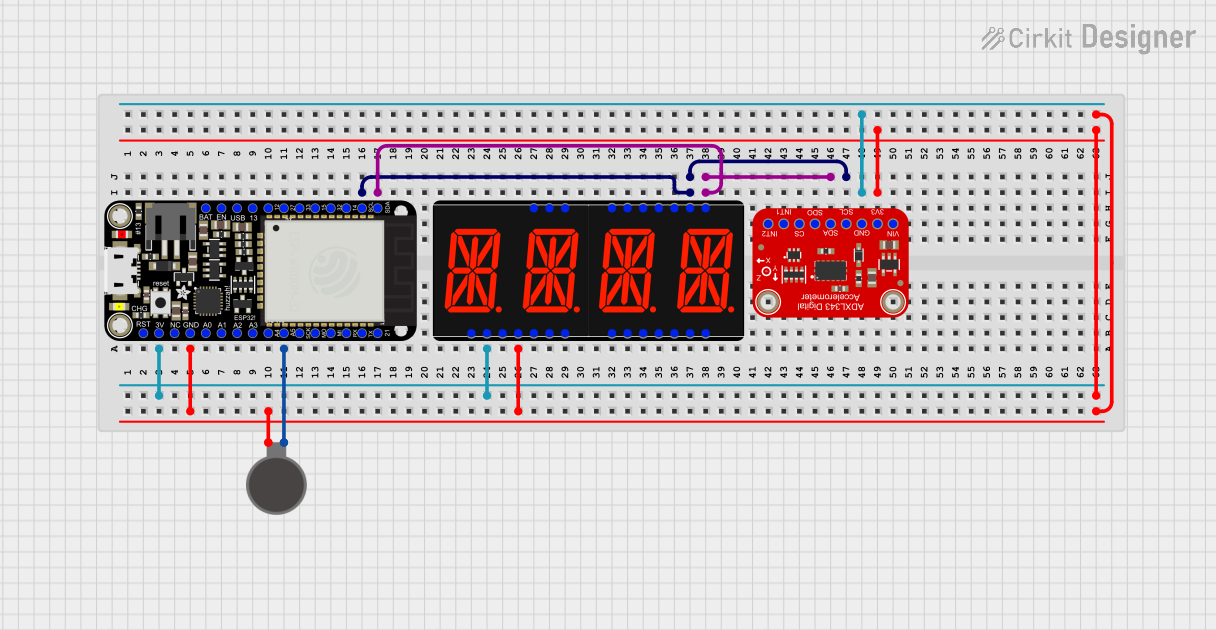 Open Project in Cirkit Designer
Explore Projects Built with Adafruit DRV2605L Haptic Motor Controller - STEMMA QT
Open Project in Cirkit DesignerOpen Project in Cirkit DesignerOpen Project in Cirkit DesignerOpen Project in Cirkit DesignerCommon Applications
- Wearable devices (e.g., smartwatches, fitness trackers)
- Gaming controllers and joysticks
- Touchscreen devices with tactile feedback
- Medical devices requiring vibration alerts
- Robotics and automation systems
Technical Specifications
The following table outlines the key technical details of the Adafruit DRV2605L Haptic Motor Controller:
| Parameter | Value |
|---|---|
| Operating Voltage | 3.0V to 5.5V |
| Communication Interface | I²C |
| Supported Motors | ERM (Eccentric Rotating Mass) and LRA (Linear Resonant Actuator) |
| Haptic Effects Library | Built-in library with over 100 effects |
| Current Consumption | ~3mA (active), ~10µA (standby) |
| Dimensions | 25.5mm x 17.8mm x 4.6mm |
| STEMMA QT Compatibility | Yes (plug-and-play I²C connectivity) |
Pin Configuration
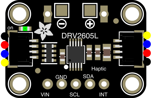
The DRV2605L module has the following pin layout:
| Pin | Name | Description |
|---|---|---|
| VIN | Power Input | Connect to 3.0V-5.5V power supply. |
| GND | Ground | Connect to the ground of the circuit. |
| SDA | I²C Data | Data line for I²C communication. |
| SCL | I²C Clock | Clock line for I²C communication. |
| IN/TRIG | Trigger Pin | Optional input for external triggering of haptic effects. |
| ACT | Active Pin | Outputs a signal when the motor is active (can be used for monitoring). |
Usage Instructions
Connecting the DRV2605L to a Circuit
- Power Supply: Connect the VIN pin to a 3.0V-5.5V power source and the GND pin to ground.
- I²C Communication: Connect the SDA and SCL pins to the corresponding I²C pins on your microcontroller (e.g., Arduino UNO).
- Motor Connection: Attach an ERM or LRA motor to the motor output terminals on the module.
- Optional Trigger: Use the IN/TRIG pin if you want to trigger haptic effects externally.
Important Considerations
- Ensure the motor you are using is compatible with the DRV2605L (ERM or LRA).
- Use pull-up resistors (typically 4.7kΩ) on the SDA and SCL lines if your microcontroller does not have internal pull-ups.
- Avoid exceeding the voltage and current ratings to prevent damage to the module.
Example Code for Arduino UNO
Below is an example of how to use the DRV2605L with an Arduino UNO to play a haptic effect:
#include <Wire.h>
#include <Adafruit_DRV2605.h>

// Create an instance of the DRV2605L library
Adafruit_DRV2605 drv;

void setup() {
  Serial.begin(9600); // Initialize serial communication for debugging
  Serial.println("Initializing DRV2605L...");

  // Initialize the DRV2605L
  if (!drv.begin()) {
    Serial.println("Failed to find DRV2605L. Check connections.");
    while (1); // Halt execution if initialization fails
  }
  Serial.println("DRV2605L initialized successfully!");

  // Select the ERM motor mode (default)
  drv.selectLibrary(1);

  // Set the haptic effect to play (e.g., effect #1)
  drv.setMode(DRV2605_MODE_INTTRIG); // Internal trigger mode
  drv.setWaveform(0, 1); // Play effect #1
  drv.setWaveform(1, 0); // End of sequence
}

void loop() {
  Serial.println("Playing haptic effect...");
  drv.go(); // Start the haptic effect
  delay(1000); // Wait for 1 second
}
Best Practices
- Use the built-in haptic effects library to simplify development.
- For custom effects, refer to the DRV2605L datasheet for waveform programming.
- Keep I²C lines as short as possible to minimize noise and ensure reliable communication.
Troubleshooting and FAQs
Common Issues
Module Not Detected on I²C Bus
- Cause: Incorrect wiring or missing pull-up resistors.
- Solution: Verify SDA and SCL connections and ensure pull-up resistors are in place.
Motor Not Vibrating
- Cause: Incompatible motor or incorrect wiring.
- Solution: Ensure the motor is an ERM or LRA type and check the motor connections.
Haptic Effects Not Playing
- Cause: Incorrect mode or waveform configuration.
- Solution: Verify that the module is in internal trigger mode and that waveforms are set correctly.
Excessive Heat
- Cause: Overvoltage or excessive current draw.
- Solution: Ensure the input voltage is within the 3.0V-5.5V range and that the motor's current rating is compatible.
FAQs
Q: Can I use multiple DRV2605L modules on the same I²C bus?
A: Yes, but you will need to use an I²C multiplexer or modify the module to change its I²C address, as the DRV2605L has a fixed address.
Q: Does the DRV2605L support custom haptic effects?
A: Yes, you can program custom waveforms by directly writing to the waveform registers.
Q: Is the DRV2605L compatible with Raspberry Pi?
A: Yes, the module can be used with Raspberry Pi via the I²C interface, but you may need to use a level shifter if operating at 3.3V logic.
Q: What is the maximum motor current supported?
A: The DRV2605L can drive motors with a current requirement of up to 250mA.
By following this documentation, you can effectively integrate the Adafruit DRV2605L Haptic Motor Controller into your projects and create engaging tactile feedback systems.