How to Use SSD1306_I2C: Examples, Pinouts, and Specs
Introduction
The SSD1306_I2C is a small OLED display driver that communicates via the I2C protocol, enabling seamless integration with microcontrollers. It supports a resolution of 128x64 pixels, making it ideal for displaying text, graphics, and simple animations. This component is widely used in embedded systems, IoT devices, and DIY electronics projects due to its low power consumption and compact size.
Explore Projects Built with SSD1306_I2C

Explore Projects Built with SSD1306_I2C
Common Applications and Use Cases
- Displaying system status or sensor data in IoT devices
- Creating user interfaces for embedded systems
- Visualizing data in portable or battery-powered devices
- Educational and hobbyist projects involving microcontrollers like Arduino or Raspberry Pi
Technical Specifications
Key Technical Details
- Display Type: OLED (Organic Light Emitting Diode)
- Resolution: 128x64 pixels
- Communication Protocol: I2C (Inter-Integrated Circuit)
- Operating Voltage: 3.3V to 5V
- Current Consumption: ~20mA (typical)
- Viewing Angle: >160°
- Driver IC: SSD1306
- Dimensions: Varies by module, typically ~27mm x 27mm
- Operating Temperature: -40°C to +85°C
Pin Configuration and Descriptions
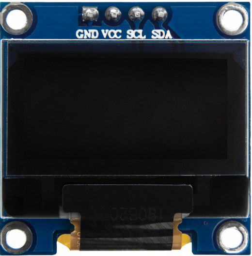
The SSD1306_I2C module typically has 4 pins. Below is the pinout:
| Pin | Name | Description |
|---|---|---|
| 1 | GND | Ground (0V reference) |
| 2 | VCC | Power supply (3.3V or 5V) |
| 3 | SCL | I2C Clock Line |
| 4 | SDA | I2C Data Line |
Usage Instructions
How to Use the SSD1306_I2C in a Circuit
Connect the Pins:
- Connect the
GNDpin to the ground of your microcontroller. - Connect the
VCCpin to a 3.3V or 5V power source, depending on your module. - Connect the
SCLpin to the I2C clock pin of your microcontroller (e.g., A5 on Arduino UNO). - Connect the
SDApin to the I2C data pin of your microcontroller (e.g., A4 on Arduino UNO).
- Connect the
Install Required Libraries:
- For Arduino, install the
Adafruit_GFXandAdafruit_SSD1306libraries via the Arduino Library Manager.
- For Arduino, install the
Write and Upload Code:
- Use the example code below to initialize and display text on the SSD1306_I2C.
Example Code for Arduino UNO
#include <Wire.h>
#include <Adafruit_GFX.h>
#include <Adafruit_SSD1306.h>

// Define the OLED display width and height
#define SCREEN_WIDTH 128
#define SCREEN_HEIGHT 64

// Create an SSD1306 display object connected via I2C
Adafruit_SSD1306 display(SCREEN_WIDTH, SCREEN_HEIGHT, &Wire, -1);

void setup() {
  // Initialize the display
  if (!display.begin(SSD1306_I2C_ADDRESS, 0x3C)) {
    // Check if the display is connected
    Serial.println(F("SSD1306 allocation failed"));
    for (;;); // Stop execution if initialization fails
  }

  // Clear the display buffer
  display.clearDisplay();

  // Set text size and color
  display.setTextSize(1); // Text size multiplier
  display.setTextColor(SSD1306_WHITE);

  // Display a message
  display.setCursor(0, 0); // Set cursor to top-left corner
  display.println(F("Hello, SSD1306!"));
  display.display(); // Render the text on the screen
}

void loop() {
  // No actions in the loop for this example
}
Important Considerations and Best Practices
- Power Supply: Ensure the module is powered with the correct voltage (3.3V or 5V) as per its specifications.
- I2C Address: The default I2C address for most SSD1306 modules is
0x3C. If the display does not respond, check the address using an I2C scanner sketch. - Pull-Up Resistors: Some modules include built-in pull-up resistors for the I2C lines. If your module does not, you may need to add external pull-up resistors (4.7kΩ to 10kΩ) on the
SCLandSDAlines. - Library Compatibility: Always use the latest versions of the
Adafruit_GFXandAdafruit_SSD1306libraries for optimal performance.
Troubleshooting and FAQs
Common Issues and Solutions
Display Not Turning On:
- Verify the power connections and ensure the correct voltage is supplied.
- Check the I2C address and update it in the code if necessary.
Text or Graphics Not Displaying:
- Ensure the
Adafruit_SSD1306library is correctly installed. - Confirm that the
display.display()function is called after drawing operations.
- Ensure the
Flickering or Unstable Display:
- Check the I2C connections for loose wires or poor soldering.
- Add pull-up resistors to the
SCLandSDAlines if not already present.
I2C Communication Errors:
- Use an I2C scanner sketch to confirm the module's address.
- Ensure no other devices on the I2C bus are causing address conflicts.
FAQs
Q: Can I use the SSD1306_I2C with a 5V microcontroller?
A: Yes, most SSD1306 modules are compatible with both 3.3V and 5V logic levels. However, always check the module's datasheet to confirm.
Q: How do I display custom graphics?
A: You can use the Adafruit_GFX library's functions to draw shapes, bitmaps, and more. Refer to the library documentation for details.
Q: What is the maximum I2C bus length for this module?
A: The I2C bus length should typically not exceed 1 meter. For longer distances, consider using I2C bus extenders.
Q: Can I use multiple SSD1306 displays on the same I2C bus?
A: Yes, but each display must have a unique I2C address. Some modules allow address changes via solder jumpers.
By following this documentation, you can effectively integrate and troubleshoot the SSD1306_I2C OLED display in your projects.