How to Use MAX471: Examples, Pinouts, and Specs
Introduction
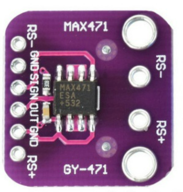
The MAX471, manufactured by Analog Devices Inc., is a high-side current sensing amplifier designed for accurate current measurement in a circuit. It features a low offset voltage and a high common-mode voltage range, making it ideal for applications requiring precise current monitoring. The MAX471 is commonly used in battery management systems, power monitoring, and motor control circuits. Its compact design and ease of integration make it a popular choice for both industrial and consumer electronics.
Explore Projects Built with MAX471


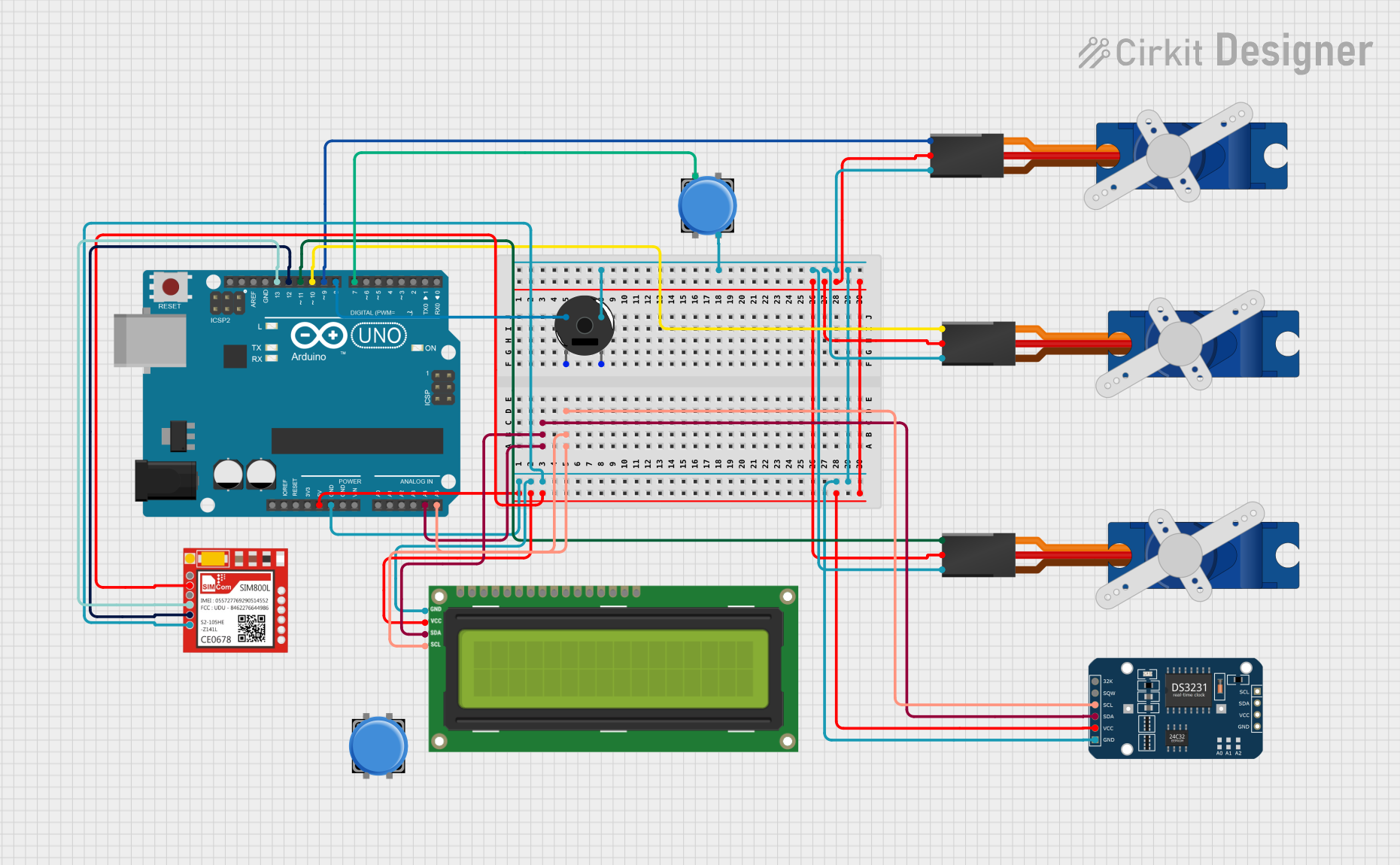

Explore Projects Built with MAX471
Common Applications:
- Battery management systems
- Power supply monitoring
- Motor control circuits
- Overcurrent protection
- Energy metering
Technical Specifications
The MAX471 is designed to provide reliable and accurate current sensing with minimal external components. Below are its key technical specifications:
| Parameter | Value |
|---|---|
| Supply Voltage (Vcc) | 3V to 36V |
| Common-Mode Voltage Range | 3V to 36V |
| Output Voltage Range | 0V to Vcc |
| Input Offset Voltage | ±2mV (typical) |
| Gain | 1V/A |
| Maximum Load Current | 3A |
| Operating Temperature Range | -40°C to +85°C |
| Package Type | 8-pin SOIC |
Pin Configuration and Descriptions
The MAX471 is available in an 8-pin SOIC package. Below is the pinout and description:
| Pin Number | Pin Name | Description |
|---|---|---|
| 1 | V+ | Positive supply voltage (3V to 36V). |
| 2 | RS+ | Positive terminal of the sense resistor. |
| 3 | RS- | Negative terminal of the sense resistor. |
| 4 | OUT | Output voltage proportional to the measured current. |
| 5 | GND | Ground connection. |
| 6 | NC | No connection (leave unconnected). |
| 7 | NC | No connection (leave unconnected). |
| 8 | V- | Negative supply voltage (typically connected to ground). |
Usage Instructions
The MAX471 is straightforward to use in a circuit for current sensing. Below are the steps and considerations for proper usage:
Circuit Connection
- Power Supply: Connect the V+ pin to a supply voltage between 3V and 36V. Connect the V- pin to ground.
- Sense Resistor: Place a low-value sense resistor (e.g., 0.1Ω) between the RS+ and RS- pins. The voltage drop across this resistor is used to measure current.
- Output: The OUT pin provides a voltage proportional to the current flowing through the sense resistor. This output can be connected to an ADC (Analog-to-Digital Converter) for further processing.
- Load Connection: Connect the load in series with the sense resistor to measure the current flowing through it.
Important Considerations
- Sense Resistor Selection: Choose a resistor with a low resistance value to minimize power loss, but ensure it is large enough to produce a measurable voltage drop.
- Bypass Capacitor: Place a decoupling capacitor (e.g., 0.1µF) close to the V+ pin to reduce noise.
- Output Filtering: If the output signal is noisy, add a low-pass filter to smooth the signal.
- Thermal Management: Ensure the sense resistor can handle the power dissipation without overheating.
Example: Using MAX471 with Arduino UNO
The MAX471 can be easily interfaced with an Arduino UNO to measure current. Below is an example circuit and code:
Circuit Diagram
- Connect the V+ pin to the Arduino's 5V pin.
- Connect the V- pin to the Arduino's GND pin.
- Connect the OUT pin to an analog input pin (e.g., A0) on the Arduino.
- Place a 0.1Ω sense resistor between RS+ and RS-.
Arduino Code
// MAX471 Current Sensor Example with Arduino UNO
// Reads current from the MAX471 and displays it on the Serial Monitor

const int sensorPin = A0; // Analog pin connected to MAX471 OUT pin
const float sensitivity = 1.0; // MAX471 sensitivity is 1V/A
const float vRef = 5.0; // Reference voltage of Arduino (5V for UNO)
const int adcResolution = 1024; // 10-bit ADC resolution

void setup() {
  Serial.begin(9600); // Initialize serial communication
}

void loop() {
  int rawValue = analogRead(sensorPin); // Read ADC value from sensor
  float voltage = (rawValue * vRef) / adcResolution; // Convert ADC value to voltage
  float current = voltage / sensitivity; // Calculate current in Amperes

  // Print the current to the Serial Monitor
  Serial.print("Current: ");
  Serial.print(current, 3); // Print current with 3 decimal places
  Serial.println(" A");

  delay(1000); // Wait for 1 second before the next reading
}
Troubleshooting and FAQs
Common Issues and Solutions
No Output Voltage:
- Ensure the V+ pin is connected to a valid power supply (3V to 36V).
- Verify that the sense resistor is properly connected between RS+ and RS-.
Inaccurate Current Measurement:
- Check the value and tolerance of the sense resistor. Use a precision resistor for better accuracy.
- Ensure the output voltage is not exceeding the ADC input range of the microcontroller.
Noisy Output Signal:
- Add a low-pass filter to the output to reduce noise.
- Use a decoupling capacitor near the V+ pin to stabilize the power supply.
Overheating Sense Resistor:
- Ensure the resistor's power rating is sufficient for the current being measured.
- Use a resistor with a lower resistance value if possible, but ensure it still provides a measurable voltage drop.
FAQs
Q: Can the MAX471 measure bidirectional current?
A: No, the MAX471 is designed for unidirectional current measurement. For bidirectional current sensing, consider using a different device such as the MAX472.
Q: What is the maximum current the MAX471 can measure?
A: The MAX471 can measure currents up to 3A, depending on the value of the sense resistor and the supply voltage.
Q: Can I use the MAX471 with a 3.3V microcontroller?
A: Yes, the MAX471 can operate with a supply voltage as low as 3V, making it compatible with 3.3V systems.
Q: How do I calculate the power dissipation of the sense resistor?
A: Power dissipation can be calculated using the formula:
( P = I^2 \times R ),
where ( I ) is the current through the resistor and ( R ) is the resistance value.
By following this documentation, users can effectively integrate the MAX471 into their projects for accurate current sensing and monitoring.