How to Use Orange Pi Zero 3: Examples, Pinouts, and Specs
Introduction
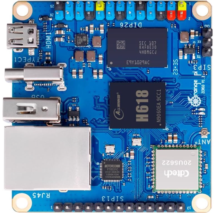
The Orange Pi Zero 3, manufactured by Xunlong Software Co., is a compact and versatile single-board computer (SBC) powered by the Allwinner H618 quad-core ARM Cortex-A53 processor. It is designed to deliver efficient performance for a wide range of applications, including IoT (Internet of Things), lightweight computing, media streaming, and embedded systems. With its small form factor, onboard Wi-Fi, Ethernet, and GPIO pins, the Orange Pi Zero 3 is an excellent choice for developers and hobbyists alike.
Explore Projects Built with Orange Pi Zero 3
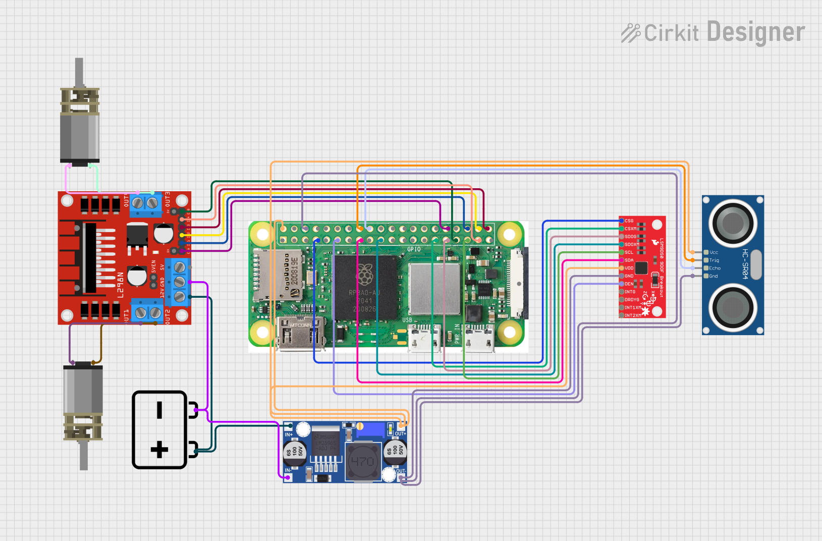
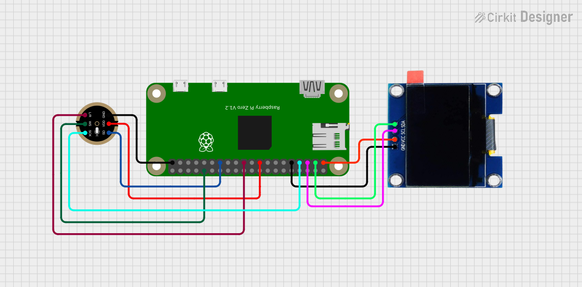

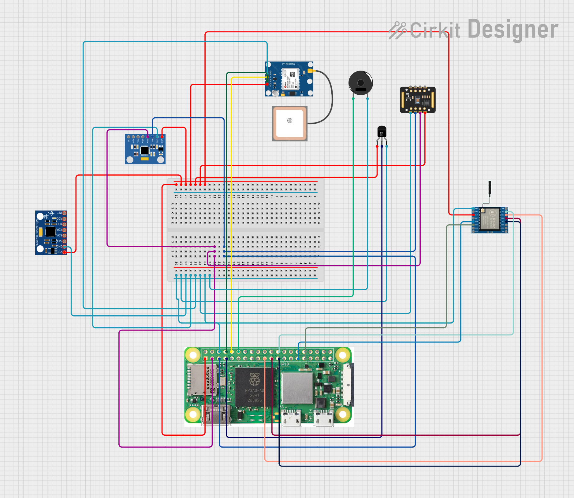
Explore Projects Built with Orange Pi Zero 3
Common Applications and Use Cases
- IoT devices and smart home automation
- Lightweight web servers and network applications
- Media streaming and playback
- Educational projects and prototyping
- Robotics and embedded systems
- Edge computing and AI/ML applications (with external accelerators)
Technical Specifications
Key Technical Details
| Specification | Details |
|---|---|
| Processor | Allwinner H618, Quad-core ARM Cortex-A53, 1.5 GHz |
| GPU | Mali-G31 MP2, supports OpenGL ES 3.2 and Vulkan 1.1 |
| RAM | 1GB or 2GB DDR4 (depending on model) |
| Storage | MicroSD card slot, eMMC module support (optional) |
| Networking | 10/100/1000 Mbps Ethernet, 2.4GHz/5GHz Wi-Fi, Bluetooth 5.0 |
| USB Ports | 1x USB 3.0, 1x USB 2.0 |
| GPIO | 26-pin GPIO header, compatible with Raspberry Pi GPIO layout |
| Power Supply | 5V/2A via USB Type-C |
| Video Output | HDMI 2.0 (4K@60fps) |
| Operating System | Android, Debian, Ubuntu, and other Linux distributions |
| Dimensions | 48mm x 48mm |
Pin Configuration and Descriptions
The Orange Pi Zero 3 features a 26-pin GPIO header. Below is the pinout and description:
| Pin Number | Pin Name | Function/Description |
|---|---|---|
| 1 | 3.3V | Power (3.3V) |
| 2 | 5V | Power (5V) |
| 3 | GPIO2 (SDA) | I2C Data |
| 4 | 5V | Power (5V) |
| 5 | GPIO3 (SCL) | I2C Clock |
| 6 | GND | Ground |
| 7 | GPIO4 | General Purpose I/O |
| 8 | GPIO14 (TXD) | UART Transmit |
| 9 | GND | Ground |
| 10 | GPIO15 (RXD) | UART Receive |
| 11 | GPIO17 | General Purpose I/O |
| 12 | GPIO18 | PWM Output |
| 13 | GPIO27 | General Purpose I/O |
| 14 | GND | Ground |
| 15 | GPIO22 | General Purpose I/O |
| 16 | GPIO23 | General Purpose I/O |
| 17 | 3.3V | Power (3.3V) |
| 18 | GPIO24 | General Purpose I/O |
| 19 | GPIO10 (MOSI) | SPI Data Out |
| 20 | GND | Ground |
| 21 | GPIO9 (MISO) | SPI Data In |
| 22 | GPIO25 | General Purpose I/O |
| 23 | GPIO11 (SCLK) | SPI Clock |
| 24 | GPIO8 (CE0) | SPI Chip Select 0 |
| 25 | GND | Ground |
| 26 | GPIO7 (CE1) | SPI Chip Select 1 |
Usage Instructions
How to Use the Orange Pi Zero 3 in a Circuit
Powering the Board:
- Use a 5V/2A power adapter with a USB Type-C connector to power the board. Ensure the power supply is stable to avoid performance issues.
Connecting Peripherals:
- Attach a monitor via the HDMI port for video output.
- Connect a keyboard and mouse using the USB ports.
- Insert a microSD card with a compatible operating system image (e.g., Debian or Ubuntu).
GPIO Usage:
- Use the 26-pin GPIO header for interfacing with sensors, actuators, or other peripherals. Refer to the pinout table for correct connections.
Networking:
- Connect to a wired network using the Ethernet port or configure Wi-Fi via the operating system.
Booting the Board:
- Insert the microSD card, connect peripherals, and power on the board. The system will boot into the pre-installed operating system.
Important Considerations and Best Practices
- Heat Management: The Orange Pi Zero 3 can get warm under heavy loads. Consider using a heatsink or fan for better thermal performance.
- Power Supply: Always use a high-quality power adapter to prevent voltage drops or instability.
- Operating System: Use official or community-supported OS images to ensure compatibility and stability.
- GPIO Precautions: Avoid exceeding the voltage and current limits of the GPIO pins to prevent damage to the board.
Example: Blinking an LED with GPIO and Arduino IDE
The Orange Pi Zero 3 can be programmed using Python or other languages. Below is an example of controlling an LED using Python's RPi.GPIO library:
Import the RPi.GPIO library
import RPi.GPIO as GPIO import time
Set the GPIO mode to BCM (Broadcom pin numbering)
GPIO.setmode(GPIO.BCM)
Define the GPIO pin connected to the LED
LED_PIN = 17
Set up the LED pin as an output
GPIO.setup(LED_PIN, GPIO.OUT)
Blink the LED in a loop
try: while True: GPIO.output(LED_PIN, GPIO.HIGH) # Turn on the LED time.sleep(1) # Wait for 1 second GPIO.output(LED_PIN, GPIO.LOW) # Turn off the LED time.sleep(1) # Wait for 1 second except KeyboardInterrupt: # Clean up GPIO settings on exit GPIO.cleanup()
---
Troubleshooting and FAQs
Common Issues and Solutions
The board does not power on:
- Ensure the power adapter provides 5V/2A and is properly connected.
- Check the USB Type-C cable for damage or poor quality.
No video output on HDMI:
- Verify that the HDMI cable is securely connected to the board and the monitor.
- Ensure the operating system image is correctly written to the microSD card.
Wi-Fi is not working:
- Check if the Wi-Fi antenna is properly connected (if applicable).
- Verify the Wi-Fi settings in the operating system.
GPIO pins are not responding:
- Ensure the correct pin numbering mode (BCM or BOARD) is used in your code.
- Double-check the wiring and connections to external components.
FAQs
Can I use a USB hub with the Orange Pi Zero 3?
Yes, you can connect a USB hub to expand the number of USB devices.What is the maximum supported microSD card size?
The board supports microSD cards up to 128GB.Does the Orange Pi Zero 3 support 4K video playback?
Yes, it supports 4K@60fps video output via the HDMI 2.0 port.Can I power the board via GPIO pins?
Yes, you can power the board using the 5V and GND pins on the GPIO header, but ensure a stable power source.
This concludes the documentation for the Orange Pi Zero 3. For further assistance, refer to the official resources provided by Xunlong Software Co.