How to Use DIP (SIM TEST): Examples, Pinouts, and Specs
DIP (SIM TEST) Documentation
1. Introduction
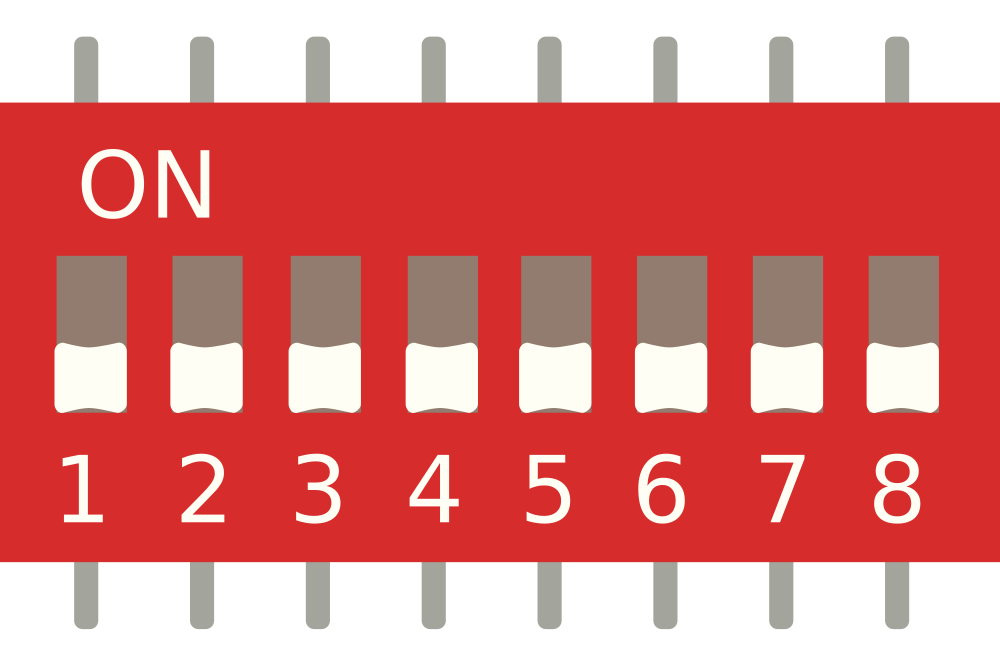
The DIP (SIM TEST) is a Dual In-line Package designed specifically for testing integrated circuits (ICs). This component allows for easy insertion and removal from a circuit board, making it an invaluable tool for simulation and testing purposes. The DIP format is widely recognized in the electronics industry, providing a standardized method for connecting ICs to circuit boards.
Common Applications and Use Cases
- Prototyping: Ideal for testing new circuit designs before finalizing PCB layouts.
- Educational Purposes: Used in laboratories and classrooms for hands-on learning about ICs.
- Debugging: Facilitates quick swapping of ICs to identify faults in a circuit.
- Simulation: Allows engineers to simulate various configurations of ICs without soldering.
2. Technical Specifications
Key Technical Details
| Specification | Value |
|---|---|
| Package Type | Dual In-line Package |
| Number of Pins | 8, 14, 16, 20, 28 |
| Maximum Voltage | 5V to 15V |
| Maximum Current | 100 mA |
| Operating Temperature | -40°C to +85°C |
Pin Configuration and Descriptions
| Pin Number | Function | Description |
|---|---|---|
| 1 | VCC | Power supply pin for the IC |
| 2 | GND | Ground connection |
| 3 | Input/Output 1 | First data line for input/output |
| 4 | Input/Output 2 | Second data line for input/output |
| 5 | Input/Output 3 | Third data line for input/output |
| 6 | Input/Output 4 | Fourth data line for input/output |
| 7 | Input/Output 5 | Fifth data line for input/output |
| 8 | Input/Output 6 | Sixth data line for input/output |
3. Usage Instructions
How to Use the Component in a Circuit
- Insert the DIP: Align the pins of the DIP with the corresponding holes on the breadboard or PCB. Ensure that the orientation is correct, with the notch or dot on the DIP matching the marking on the board.
- Connect Power and Ground: Connect the VCC pin to the power supply and the GND pin to the ground.
- Connect Input/Output Pins: Wire the input/output pins to the desired components in your circuit, such as sensors, LEDs, or microcontrollers.
Important Considerations and Best Practices
- Avoid Overheating: Do not exceed the maximum voltage and current ratings to prevent damage.
- Use Proper Tools: Utilize a DIP extractor tool for safe removal of the component from the circuit.
- Check Orientation: Always double-check the orientation of the DIP before powering the circuit to avoid short circuits.
4. Troubleshooting and FAQs
Common Issues Users Might Face
- Component Not Responding: The DIP may not be properly seated in the socket.
- Incorrect Output: Check the wiring of the input/output pins for any mistakes.
- Overheating: Ensure that the voltage and current ratings are not exceeded.
Solutions and Tips for Troubleshooting
- Reseat the Component: Remove and reinsert the DIP to ensure a good connection.
- Verify Connections: Use a multimeter to check for continuity in the circuit.
- Consult Datasheets: Refer to the datasheet of the specific IC being tested for additional information.
Example Arduino Code
If you are using the DIP with an Arduino UNO, here is a simple code snippet to read from an input pin:
const int inputPin = 2; // Pin connected to Input/Output 1 of DIP

void setup() {
  Serial.begin(9600); // Start serial communication
  pinMode(inputPin, INPUT); // Set the pin as input
}

void loop() {
  int value = digitalRead(inputPin); // Read the input value
  Serial.println(value); // Print the value to the Serial Monitor
  delay(1000); // Wait for 1 second
}
This code initializes the input pin and continuously reads its value, printing it to the Serial Monitor every second. Make sure to connect the appropriate output from the DIP to pin 2 of the Arduino UNO.
By following this documentation, users can effectively utilize the DIP (SIM TEST) for various applications in electronics testing and prototyping.
Explore Projects Built with DIP (SIM TEST)


Explore Projects Built with DIP (SIM TEST)