How to Use IR Sensor : Examples, Pinouts, and Specs
Introduction
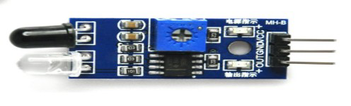
The IR Sensor (Manufacturer: JLC PCB, Part ID: UNO) is a versatile electronic component designed to detect infrared (IR) radiation. It is widely used in applications such as proximity sensing, motion detection, and remote control systems. The sensor operates by emitting and/or detecting IR light, making it suitable for both reflective and transmissive sensing tasks.
Common applications include:
- Obstacle detection in robotics
- Line-following robots
- Motion detection in security systems
- Remote control signal reception
- Non-contact temperature measurement
Explore Projects Built with IR Sensor
Explore Projects Built with IR Sensor
Technical Specifications
The following table outlines the key technical details of the IR Sensor:
| Parameter | Specification |
|---|---|
| Operating Voltage | 3.3V - 5V |
| Operating Current | 20mA (typical) |
| Detection Range | 2cm - 30cm (adjustable) |
| Output Type | Digital (High/Low) |
| Wavelength Sensitivity | 760nm - 1100nm (Infrared range) |
| Response Time | < 2ms |
| Operating Temperature | -25°C to 85°C |
Pin Configuration and Descriptions
The IR Sensor typically has three pins. The table below describes each pin:
| Pin Number | Pin Name | Description |
|---|---|---|
| 1 | VCC | Power supply pin (3.3V - 5V) |
| 2 | GND | Ground pin |
| 3 | OUT | Digital output pin (High when no object detected, Low when object detected) |
Usage Instructions
How to Use the IR Sensor in a Circuit
- Power the Sensor: Connect the
VCCpin to a 3.3V or 5V power source and theGNDpin to the ground of your circuit. - Connect the Output: Attach the
OUTpin to a digital input pin of your microcontroller or to an external circuit for further processing. - Adjust the Sensitivity: Use the onboard potentiometer (if available) to adjust the detection range of the sensor.
- Test the Sensor: Place an object within the detection range and observe the output signal on the
OUTpin.
Important Considerations and Best Practices
- Ambient Light Interference: Avoid using the sensor in environments with strong IR sources (e.g., direct sunlight) as it may affect accuracy.
- Mounting Distance: Ensure the sensor is mounted at an appropriate distance from the object to be detected, within its specified range.
- Power Supply Stability: Use a stable power supply to avoid erratic behavior.
- Avoid Overvoltage: Do not exceed the maximum operating voltage of 5V to prevent damage to the sensor.
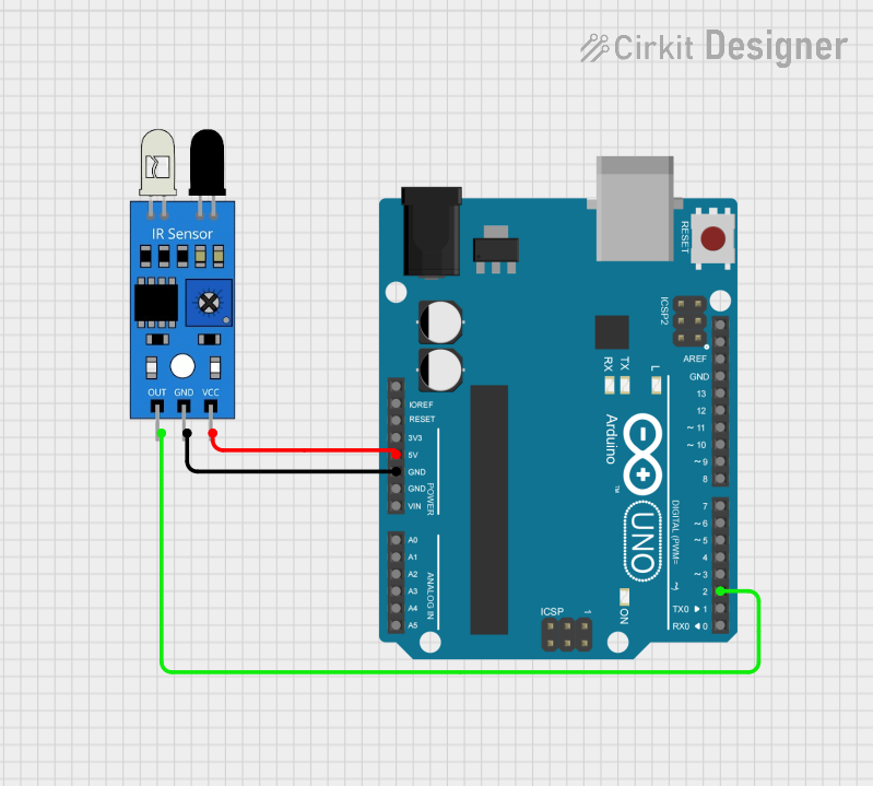
Example: Connecting the IR Sensor to an Arduino UNO
Below is an example of how to connect and use the IR Sensor with an Arduino UNO:
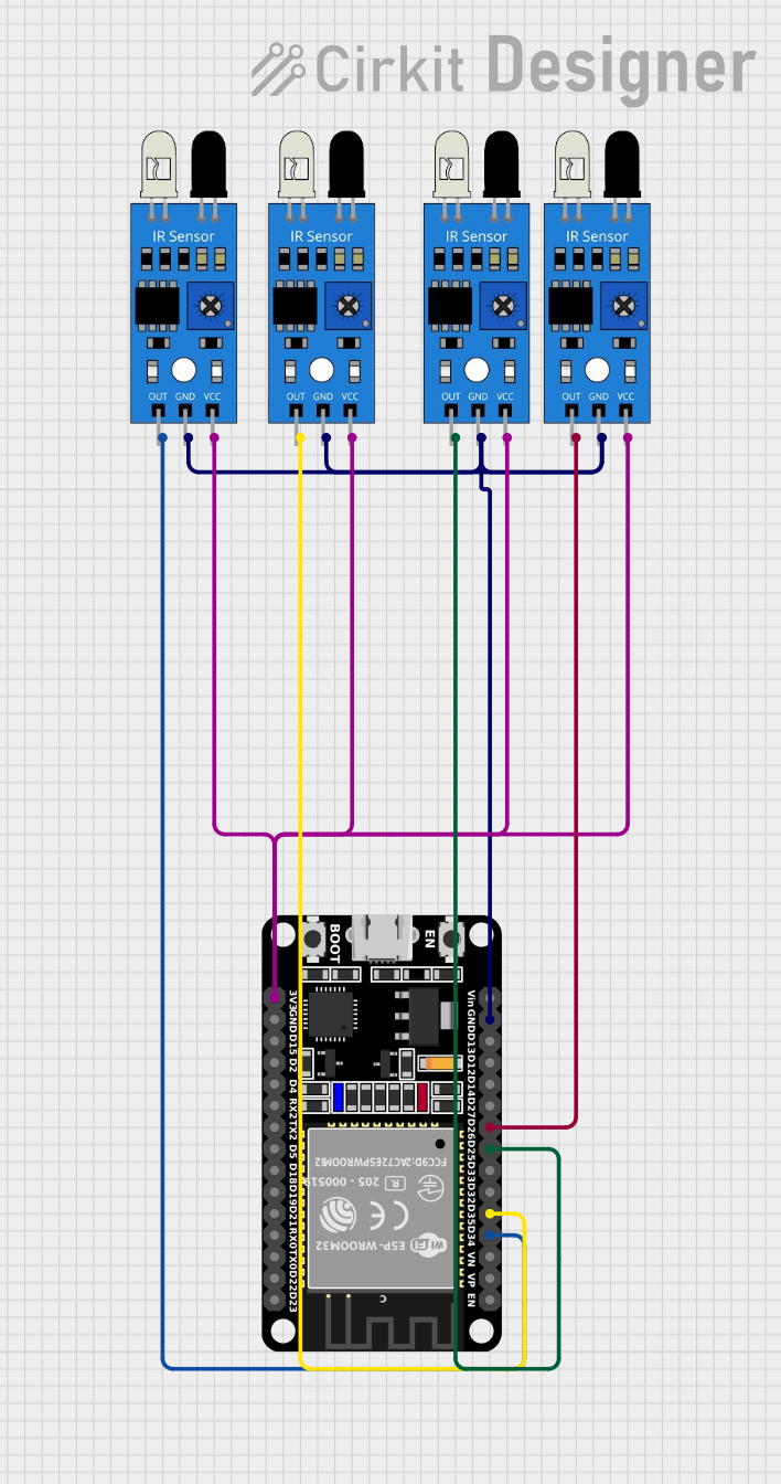
Circuit Diagram
- Connect the
VCCpin of the IR Sensor to the 5V pin on the Arduino. - Connect the
GNDpin of the IR Sensor to the GND pin on the Arduino. - Connect the
OUTpin of the IR Sensor to digital pin 2 on the Arduino.
Arduino Code
// IR Sensor Example Code for Arduino UNO
// This code reads the output of the IR sensor and prints the status to the Serial Monitor.

const int irSensorPin = 2; // IR sensor output connected to digital pin 2
int sensorValue = 0;       // Variable to store the sensor reading

void setup() {
  pinMode(irSensorPin, INPUT); // Set the IR sensor pin as input
  Serial.begin(9600);          // Initialize serial communication at 9600 baud
}

void loop() {
  sensorValue = digitalRead(irSensorPin); // Read the sensor output
  if (sensorValue == LOW) {
    // Object detected
    Serial.println("Object detected!");
  } else {
    // No object detected
    Serial.println("No object detected.");
  }
  delay(500); // Wait for 500ms before the next reading
}
Troubleshooting and FAQs
Common Issues and Solutions
Sensor Not Detecting Objects
- Cause: Incorrect wiring or insufficient power supply.
- Solution: Double-check the connections and ensure the power supply is stable and within the specified range.
False Positives or Erratic Behavior
- Cause: Ambient IR interference or unstable power supply.
- Solution: Shield the sensor from strong IR sources and use a decoupling capacitor (e.g., 0.1µF) across the power pins.
Short Detection Range
- Cause: Sensitivity not properly adjusted.
- Solution: Use the onboard potentiometer to increase the detection range.
Output Always High or Low
- Cause: Faulty sensor or incorrect pin connections.
- Solution: Test the sensor with a multimeter or replace it if necessary. Verify the pin connections.
FAQs
Q1: Can the IR Sensor detect transparent objects?
A1: No, the IR Sensor may not reliably detect transparent objects as they do not reflect sufficient IR light.
Q2: Can I use the IR Sensor with a 3.3V microcontroller?
A2: Yes, the sensor operates within a voltage range of 3.3V to 5V, making it compatible with 3.3V systems.
Q3: How do I increase the detection range?
A3: Adjust the onboard potentiometer to increase the sensitivity and detection range.
Q4: Can the IR Sensor detect heat?
A4: No, this sensor is designed to detect reflected IR light, not heat. For heat detection, use a thermal IR sensor.
By following this documentation, you can effectively integrate and troubleshoot the IR Sensor in your projects.