How to Use NAZE 32: Examples, Pinouts, and Specs
Introduction
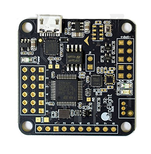
The NAZE 32, manufactured by Shivansh Rikhari, is a versatile flight controller designed for drones and other Unmanned Aerial Vehicles (UAVs). It provides stabilization and control by processing sensor data and user inputs, ensuring smooth and responsive flight performance. The NAZE 32 is built around the STM32F103CBT6 microcontroller, offering robust performance and a range of features suitable for both hobbyists and professional drone enthusiasts.
Explore Projects Built with NAZE 32
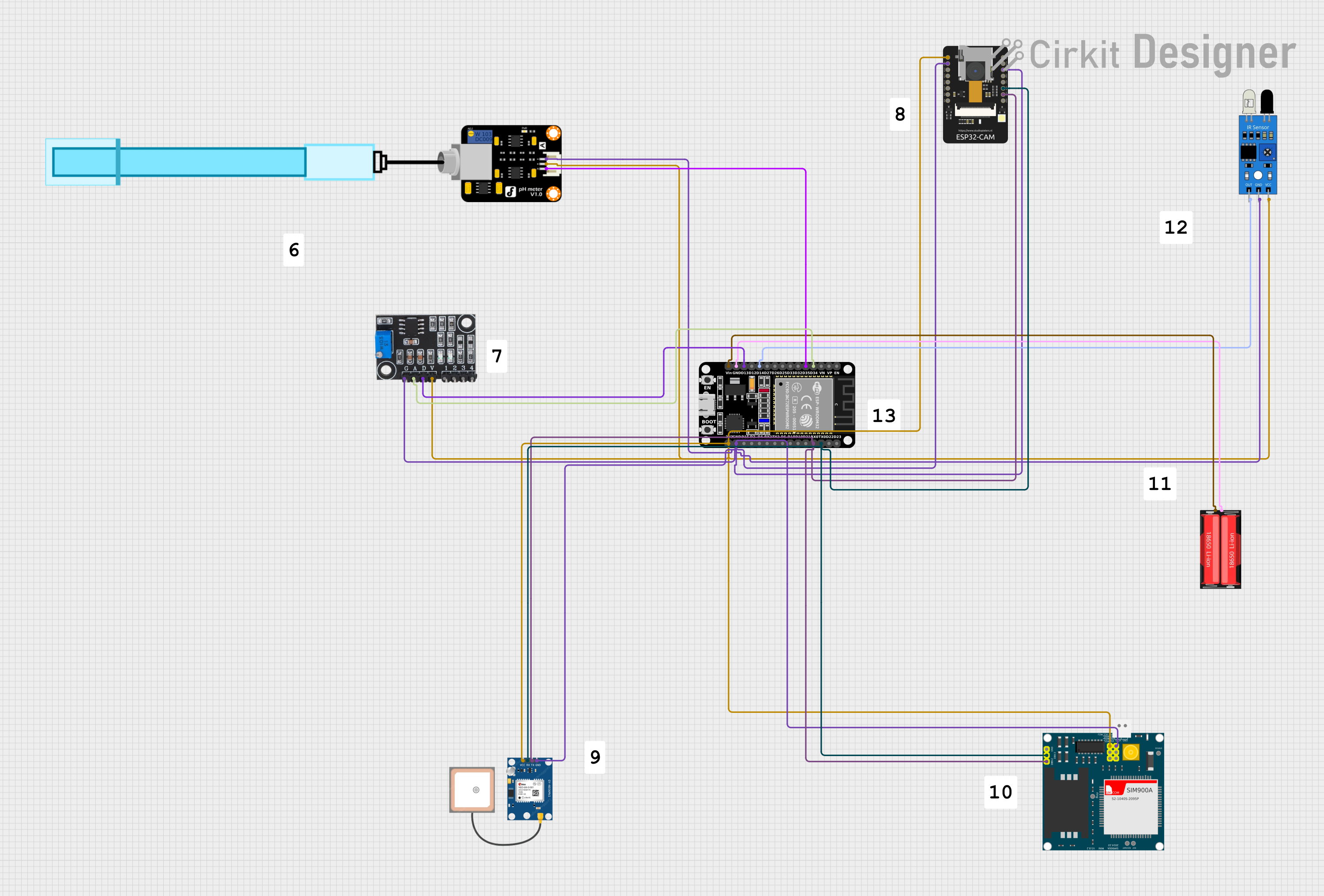
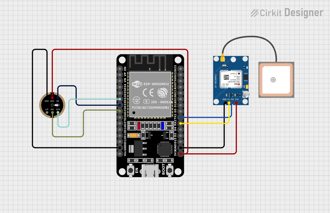
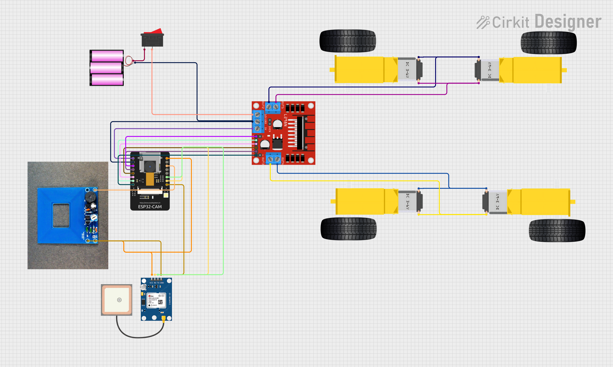
Explore Projects Built with NAZE 32
Common Applications and Use Cases
- Quadcopters and Multirotors: Provides stabilization and control for various multirotor configurations.
- Fixed-Wing Aircraft: Enhances flight stability and control for fixed-wing UAVs.
- FPV Racing Drones: Offers high-speed processing for responsive control in racing scenarios.
- Aerial Photography and Videography: Ensures smooth flight for capturing high-quality aerial footage.
Technical Specifications
Key Technical Details
| Specification | Value |
|---|---|
| Microcontroller | STM32F103CBT6 |
| Input Voltage | 5V |
| Operating Voltage | 3.3V |
| Processor Speed | 72 MHz |
| Flash Memory | 128 KB |
| RAM | 20 KB |
| Gyroscope | MPU6050 |
| Accelerometer | MPU6050 |
| Barometer | BMP180 (optional) |
| Magnetometer | HMC5883L (optional) |
| Dimensions | 36mm x 36mm |
| Weight | 6 grams |
Pin Configuration and Descriptions
| Pin Number | Pin Name | Description |
|---|---|---|
| 1 | GND | Ground |
| 2 | 5V | 5V Power Input |
| 3 | 3.3V | 3.3V Power Output |
| 4 | RX1 | UART1 Receive |
| 5 | TX1 | UART1 Transmit |
| 6 | RX2 | UART2 Receive |
| 7 | TX2 | UART2 Transmit |
| 8 | SCL | I2C Clock |
| 9 | SDA | I2C Data |
| 10 | PWM1 | PWM Output 1 (Motor 1) |
| 11 | PWM2 | PWM Output 2 (Motor 2) |
| 12 | PWM3 | PWM Output 3 (Motor 3) |
| 13 | PWM4 | PWM Output 4 (Motor 4) |
| 14 | PWM5 | PWM Output 5 (Auxiliary) |
| 15 | PWM6 | PWM Output 6 (Auxiliary) |
| 16 | PWM7 | PWM Output 7 (Auxiliary) |
| 17 | PWM8 | PWM Output 8 (Auxiliary) |
| 18 | ADC1 | Analog Input 1 |
| 19 | ADC2 | Analog Input 2 |
| 20 | ADC3 | Analog Input 3 |
Usage Instructions
How to Use the NAZE 32 in a Circuit
Power Supply:
- Connect the 5V power input to a stable 5V power source.
- Ensure the ground (GND) is connected to the common ground of the circuit.
Motor Connections:
- Connect the motors to the PWM output pins (PWM1 to PWM4 for a quadcopter).
Sensor Connections:
- If using external sensors, connect them to the appropriate I2C or ADC pins.
Receiver Connections:
- Connect the receiver to the UART pins (RX1, TX1) for communication.
Flight Software:
- Flash the appropriate flight control firmware (e.g., Cleanflight, Betaflight) to the NAZE 32 using a USB connection.
Important Considerations and Best Practices
- Calibration: Always calibrate the accelerometer and gyroscope before the first flight.
- Firmware Updates: Regularly update the firmware to benefit from the latest features and improvements.
- Power Supply: Ensure a stable power supply to avoid brownouts and potential crashes.
- Vibration Dampening: Use vibration dampening materials to reduce sensor noise and improve flight stability.
Troubleshooting and FAQs
Common Issues and Solutions
Issue: Flight controller not powering on.
- Solution: Check the power connections and ensure the 5V supply is stable.
Issue: Motors not spinning.
- Solution: Verify the motor connections to the PWM pins and ensure the ESCs are properly calibrated.
Issue: Unstable flight.
- Solution: Calibrate the accelerometer and gyroscope. Check for vibrations and use dampening materials if necessary.
Issue: No communication with the receiver.
- Solution: Ensure the receiver is properly connected to the UART pins and configured correctly in the flight software.
FAQs
Q: Can I use the NAZE 32 with an Arduino UNO? A: Yes, you can interface the NAZE 32 with an Arduino UNO using the UART pins for communication. Below is an example code snippet for reading data from the NAZE 32:
#include <SoftwareSerial.h>

SoftwareSerial NAZE32(10, 11); // RX, TX

void setup() {
  Serial.begin(9600);
  NAZE32.begin(115200); // Set baud rate to match NAZE 32
}

void loop() {
  if (NAZE32.available()) {
    char c = NAZE32.read();
    Serial.print(c); // Print data from NAZE 32 to Serial Monitor
  }
}
Q: How do I update the firmware on the NAZE 32? A: Use a USB connection to connect the NAZE 32 to your computer. Open the flight control software (e.g., Betaflight Configurator), select the appropriate firmware, and follow the on-screen instructions to flash the firmware.
Q: What sensors are integrated into the NAZE 32? A: The NAZE 32 includes an MPU6050 gyroscope and accelerometer. Optional sensors include the BMP180 barometer and HMC5883L magnetometer.
By following this documentation, users can effectively utilize the NAZE 32 flight controller in their UAV projects, ensuring stable and responsive flight performance.