How to Use MAX32664: Examples, Pinouts, and Specs
Introduction
The MAX32664 is a versatile, low-power microcontroller designed by Maxim Integrated, featuring a built-in 2MB flash memory, advanced peripherals, and a Floating Point Unit (FPU). It is specifically tailored for applications in wearable devices, Internet of Things (IoT), and connected healthcare due to its power efficiency and processing capabilities. The MAX32664 enables designers to develop sophisticated applications that require complex mathematical computations and algorithm processing while maintaining low energy consumption.
Explore Projects Built with MAX32664


Explore Projects Built with MAX32664
Common Applications and Use Cases
- Wearable Health Monitors
- Fitness Trackers
- Smart Watches
- IoT Sensors and Nodes
- Remote Healthcare Devices
- Biometric Authentication Systems
Technical Specifications
Key Technical Details
- Core: 32-bit ARM® Cortex®-M4 with FPU
- Operating Voltage: 1.71V to 3.6V
- Flash Memory: 2MB
- RAM: 256KB
- Communication Interfaces: I²C, SPI, UART
- GPIOs: Multiple, configurable
- ADC: 10-bit, 1Msps
- Power Consumption: Ultra-low power modes available
- Temperature Range: -40°C to +85°C
Pin Configuration and Descriptions
| Pin Number | Name | Description |
|---|---|---|
| 1 | VDD | Power supply voltage |
| 2 | GND | Ground connection |
| 3 | SCL | I²C clock line |
| 4 | SDA | I²C data line |
| 5 | MISO | SPI Master In Slave Out |
| 6 | MOSI | SPI Master Out Slave In |
| 7 | SCK | SPI clock line |
| 8 | RXD | UART receive data |
| 9 | TXD | UART transmit data |
| 10 | ADC0 | Analog-to-digital converter input 0 |
| ... | ... | ... |
| n | GPIOx | General-purpose input/output x |
Note: This is a simplified representation. Refer to the MAX32664 datasheet for the complete pinout and package options.
Usage Instructions
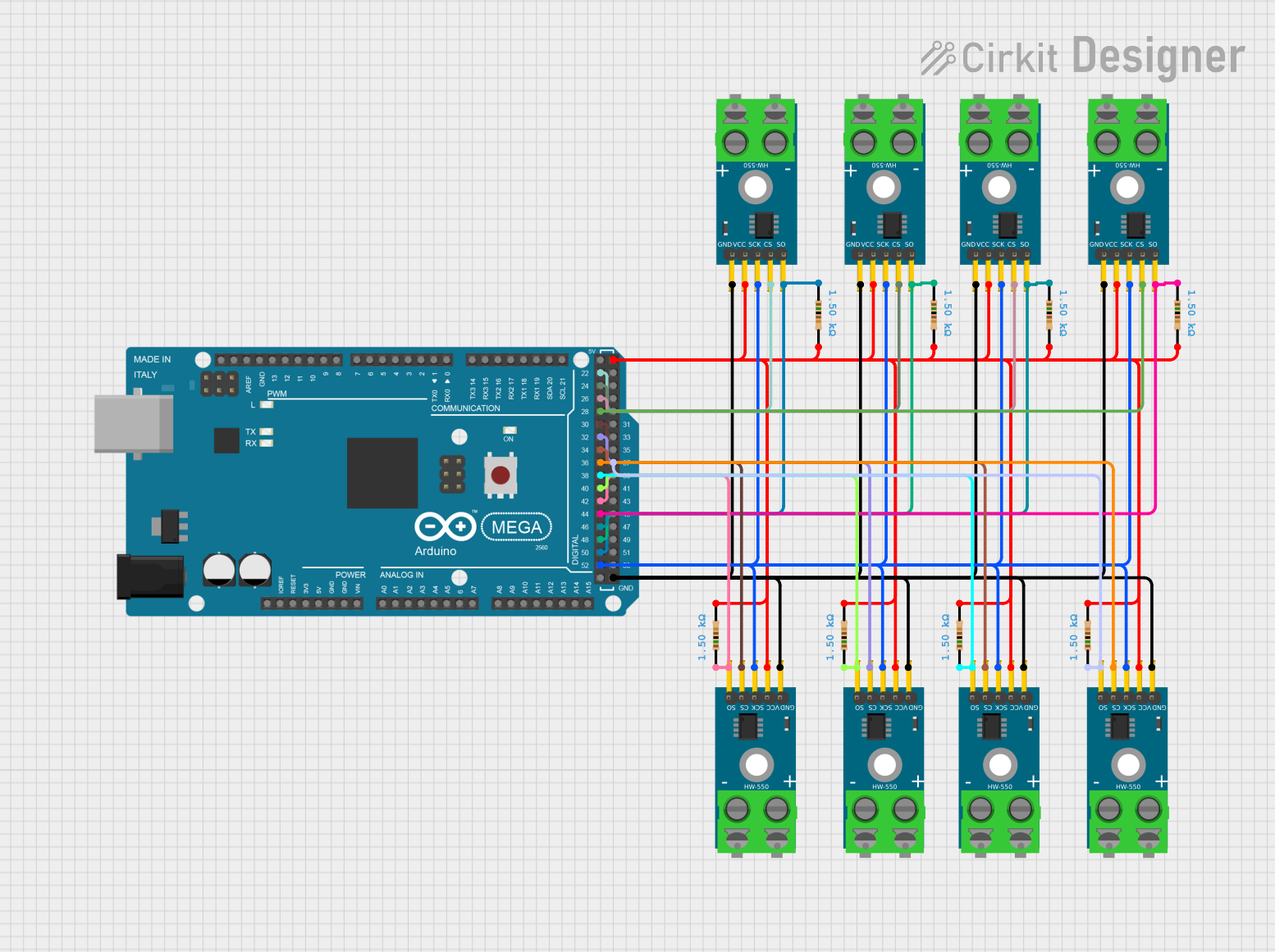
How to Use the Component in a Circuit
- Power Supply: Connect the VDD pin to a power source within the operating voltage range and GND to the common ground.
- Programming: Use the appropriate interface (I²C, SPI, UART) for programming the device and communication with other peripherals.
- GPIO Configuration: Configure the GPIO pins according to the requirements of your application, whether it's for input sensing or output control.
- ADC Usage: Connect analog sensors to ADC pins for digital conversion and processing within the microcontroller.
Important Considerations and Best Practices
- Ensure that the power supply is clean and within the specified voltage range to prevent damage.
- Use decoupling capacitors close to the power pins to stabilize the power supply.
- Avoid running the microcontroller at its maximum ratings for extended periods to ensure longevity.
- Implement proper ESD precautions when handling the microcontroller to prevent static damage.
- Follow the recommended PCB layout guidelines as specified in the datasheet for optimal performance.
Troubleshooting and FAQs
Common Issues Users Might Face
- Device Not Powering Up: Check the power supply connections and voltages. Ensure that the power supply is within the operating range.
- Communication Errors: Verify the integrity of the communication lines and ensure that the correct protocols and speeds are being used.
- Unexpected Behavior: Ensure that the GPIOs are correctly configured. Check for software bugs or memory issues.
Solutions and Tips for Troubleshooting
- Always double-check connections and solder joints for any shorts or opens.
- Use a logic analyzer or oscilloscope to debug communication issues.
- Perform a factory reset if the device is not responding as expected and reprogram it.
- Consult the datasheet and user manual for detailed troubleshooting steps.
FAQs
Q: Can the MAX32664 be used in battery-powered applications? A: Yes, the MAX32664 is designed for low-power applications and is suitable for battery-powered devices.
Q: Does the MAX32664 support wireless communication? A: The MAX32664 does not have built-in wireless capabilities, but it can interface with external wireless modules via its communication interfaces.
Q: What development tools are available for the MAX32664? A: Maxim Integrated provides a range of development tools, including software libraries, development boards, and an integrated development environment (IDE) for the MAX32664.
Q: How can I minimize power consumption when using the MAX32664? A: Utilize the low-power modes available, minimize active peripherals when not in use, and optimize your code for efficiency.
Example Code for Arduino UNO
// Example code for interfacing MAX32664 with Arduino UNO via I2C

#include <Wire.h>

// MAX32664 I2C address (check datasheet for the correct address)
#define MAX32664_ADDR 0x55

void setup() {
  Wire.begin(); // Initialize I2C
  Serial.begin(9600); // Start serial communication at 9600 baud rate

  // Configure MAX32664 (example configuration)
  Wire.beginTransmission(MAX32664_ADDR);
  Wire.write(0x00); // Control register address
  Wire.write(0x01); // Control register value to initialize the device
  Wire.endTransmission();
}

void loop() {
  // Read data from MAX32664 (example read operation)
  Wire.beginTransmission(MAX32664_ADDR);
  Wire.write(0x01); // Data register address
  Wire.endTransmission(false);
  Wire.requestFrom(MAX32664_ADDR, 1); // Request 1 byte of data

  if (Wire.available()) {
    byte data = Wire.read(); // Read the data
    Serial.print("Data: ");
    Serial.println(data, HEX); // Print the data in hexadecimal format
  }

  delay(1000); // Wait for 1 second
}
Note: This example code is for illustrative purposes and may require modifications to work with specific hardware setups. Always refer to the MAX32664 datasheet and your microcontroller's documentation when writing actual code.