How to Use R4 MINIMA: Examples, Pinouts, and Specs
Introduction
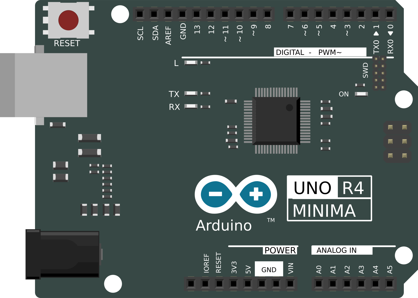
The R4 MINIMA is a high-precision resistor engineered to deliver minimal thermal and electrical noise. It is specifically designed for use in sensitive electronic circuits where signal integrity and accuracy are paramount. With its exceptional stability and low noise characteristics, the R4 MINIMA is ideal for applications such as audio processing, instrumentation, medical devices, and precision measurement systems.
Explore Projects Built with R4 MINIMA
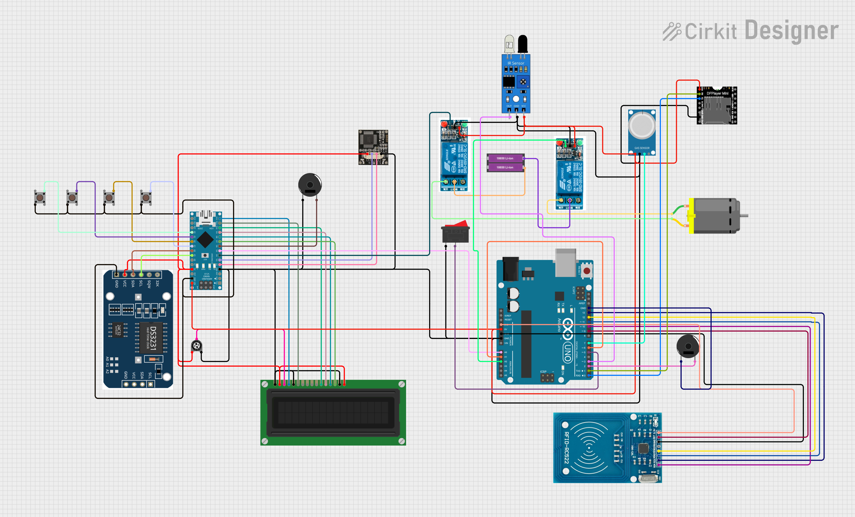
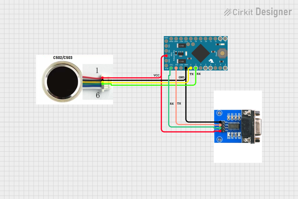
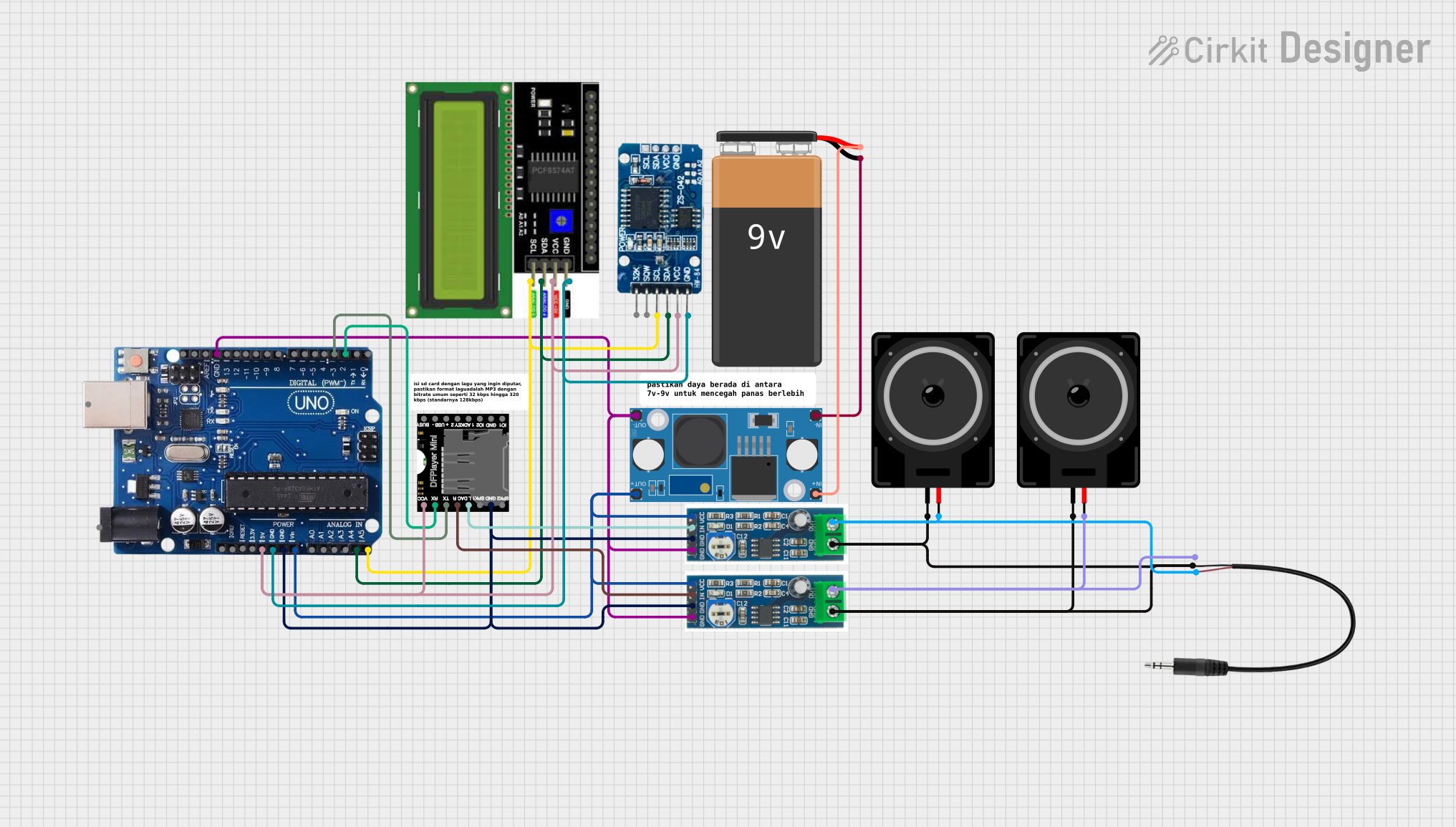

Explore Projects Built with R4 MINIMA
Common Applications:
- High-fidelity audio equipment
- Medical instrumentation
- Precision measurement circuits
- Signal processing systems
- Laboratory-grade equipment
Technical Specifications
The R4 MINIMA is available in various resistance values and tolerances to suit a wide range of applications. Below are the key technical details:
General Specifications:
| Parameter | Value |
|---|---|
| Resistance Range | 10 Ω to 1 MΩ |
| Tolerance | ±0.01% |
| Temperature Coefficient | ±2 ppm/°C |
| Power Rating | 0.25 W (1/4 W) |
| Operating Temperature | -55°C to +125°C |
| Noise | < 0.1 µV/V |
| Stability | ±0.005% over 1,000 hours |
Pin Configuration and Descriptions:
The R4 MINIMA is a two-terminal component with the following pin configuration:
| Pin Number | Description |
|---|---|
| 1 | Resistor terminal (input) |
| 2 | Resistor terminal (output) |
Usage Instructions
How to Use the R4 MINIMA in a Circuit:
- Determine the Required Resistance Value: Select the appropriate resistance value and tolerance for your application. Ensure the power rating of the resistor is sufficient for the circuit's requirements.
- Placement in the Circuit: Connect the R4 MINIMA in series or parallel as needed. Ensure proper orientation, though resistors are non-polarized components.
- Soldering: Use a soldering iron with a temperature below 300°C to avoid damaging the resistor. Minimize heat exposure by soldering quickly.
- Verify Connections: After soldering, inspect the connections to ensure there are no cold joints or shorts.
Important Considerations:
- Thermal Management: Avoid placing the resistor near heat-generating components to maintain its precision.
- Voltage Rating: Ensure the applied voltage does not exceed the resistor's maximum voltage rating.
- Noise Sensitivity: For noise-sensitive applications, use shielded cables and proper grounding techniques to minimize interference.
Example: Using R4 MINIMA with an Arduino UNO
The R4 MINIMA can be used in voltage divider circuits or as a pull-up/pull-down resistor in Arduino projects. Below is an example of using the R4 MINIMA in a voltage divider circuit to measure an analog voltage:
Circuit Diagram:
- Connect one terminal of the R4 MINIMA (e.g., 10 kΩ) to the 5V pin of the Arduino.
- Connect the other terminal to a second resistor (e.g., 10 kΩ) and then to GND.
- The junction between the two resistors is connected to an analog input pin (e.g., A0).
Arduino Code:
// Example code to read voltage from a voltage divider using R4 MINIMA
const int analogPin = A0; // Analog pin connected to the voltage divider
float voltage = 0.0;      // Variable to store the measured voltage
const float Vcc = 5.0;    // Supply voltage (5V for Arduino UNO)

void setup() {
  Serial.begin(9600); // Initialize serial communication
}

void loop() {
  int sensorValue = analogRead(analogPin); // Read the analog input
  voltage = (sensorValue / 1023.0) * Vcc;  // Convert to voltage
  Serial.print("Measured Voltage: ");
  Serial.print(voltage);
  Serial.println(" V");
  delay(1000); // Wait for 1 second before the next reading
}
Best Practices:
- Use resistors with matching tolerances in critical applications to ensure consistent performance.
- Avoid exceeding the resistor's power rating to prevent overheating and potential failure.
Troubleshooting and FAQs
Common Issues:
Incorrect Resistance Value:
- Cause: Misreading the resistor's value or selecting the wrong part.
- Solution: Double-check the resistance value using a multimeter or refer to the product datasheet.
Excessive Heat:
- Cause: Power dissipation exceeds the resistor's rating.
- Solution: Use a resistor with a higher power rating or reduce the current in the circuit.
Noise in the Circuit:
- Cause: External interference or improper grounding.
- Solution: Use shielded cables, proper grounding, and place the resistor away from noise sources.
Damaged Resistor:
- Cause: Overheating during soldering or excessive voltage/current.
- Solution: Replace the resistor and ensure proper handling during installation.
FAQs:
Q1: Can the R4 MINIMA be used in high-frequency circuits?
A1: Yes, the R4 MINIMA's low noise and high stability make it suitable for high-frequency and precision applications.
Q2: How do I calculate the power dissipation of the resistor?
A2: Use the formula ( P = I^2 \times R ), where ( P ) is power, ( I ) is current, and ( R ) is resistance.
Q3: What is the maximum voltage the R4 MINIMA can handle?
A3: The maximum voltage depends on the specific model. Refer to the datasheet for the exact value, but typically it is around 200V.
Q4: Can I use the R4 MINIMA in a high-temperature environment?
A4: Yes, the R4 MINIMA operates reliably up to +125°C. However, ensure proper thermal management to maintain precision.
By following this documentation, users can effectively integrate the R4 MINIMA into their circuits and achieve optimal performance.