Cirkit Designer
Your all-in-one circuit design IDE
Home /
Component Documentation
How to Use 16 led ring: Examples, Pinouts, and Specs
Introduction
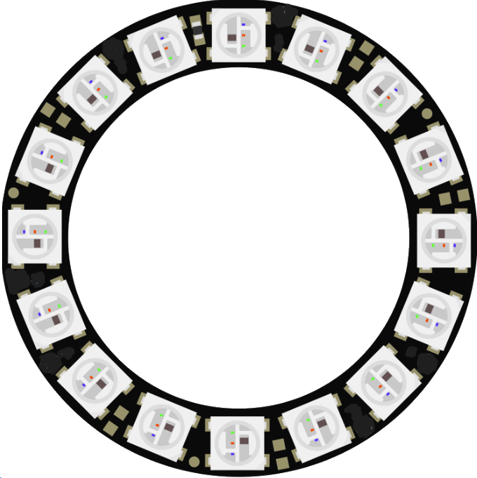
The 16 LED Ring is a circular arrangement of 16 individually addressable LEDs. This component is widely used in various electronic projects to create stunning visual effects and displays. Each LED in the ring can be controlled independently, allowing for a wide range of color and brightness combinations. The 16 LED Ring is commonly used in applications such as:
- Decorative lighting
- Status indicators
- Wearable electronics
- Interactive displays
- Robotics
Explore Projects Built with 16 led ring
Arduino UNO Controlled NeoPixel Ring Light Show
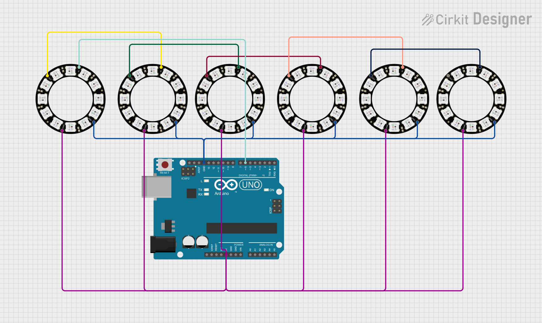
This circuit consists of an Arduino UNO microcontroller connected to six Adafruit 12 NeoPixel Rings, each with 12 LEDs, for a total of 72 LEDs. The Arduino controls the LEDs to display a yellow color with varying brightness, creating a pulsating effect.
Arduino-Controlled NeoPixel LED Display with Voltage Regulation
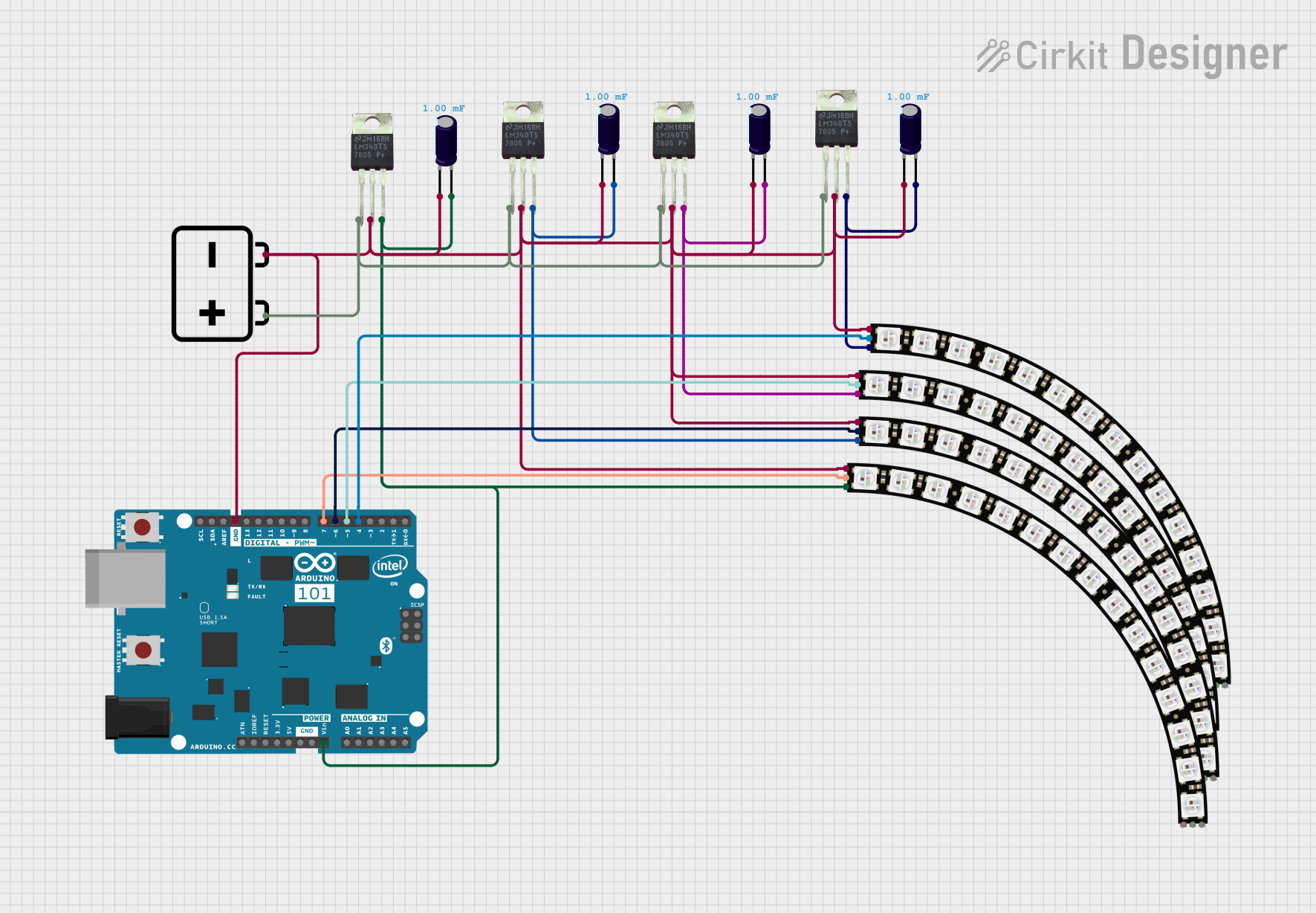
This circuit features an Arduino 101 controlling multiple individually addressable Adafruit NeoPixel LED rings, with power regulation and decoupling provided by 7805 voltage regulators and electrolytic capacitors, all powered by a 12V battery.
Wi-Fi Controlled Smart Target System with ESP8266 and NeoPixel Ring
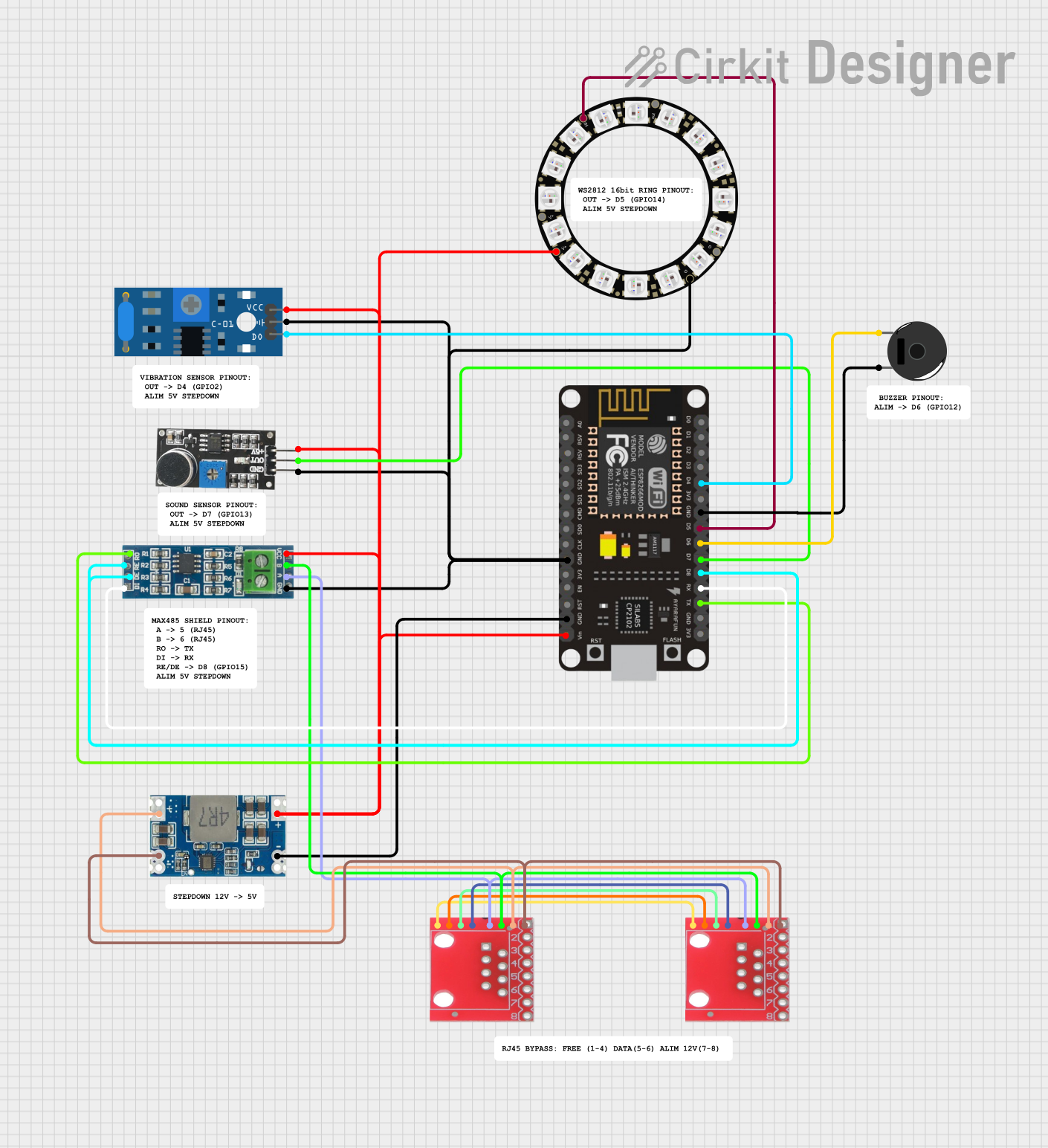
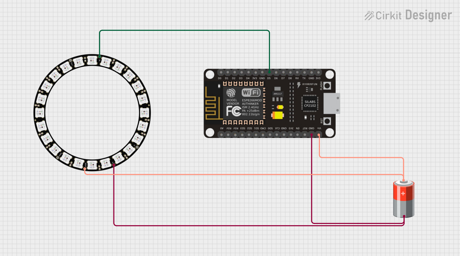
This circuit is a smart target system that uses an ESP8266 NodeMCU to control an Adafruit NeoPixel Ring, a piezo buzzer, and sensors (vibration and sound) to detect hits. The system connects to a Wi-Fi network and communicates with a server to report hit events and receive configuration updates, utilizing an RS-485 module for additional communication capabilities.
Wi-Fi Controlled NeoPixel Ring with ESP-8266 and Battery Power
This circuit features an ESP-8266 microcontroller that controls an Adafruit 24 NeoPixel Ring, powered by a 5V battery. The microcontroller is programmed to toggle a motor and an LED based on a switch input, although the motor control functionality is not connected in the provided net list.
Explore Projects Built with 16 led ring
Arduino UNO Controlled NeoPixel Ring Light Show
This circuit consists of an Arduino UNO microcontroller connected to six Adafruit 12 NeoPixel Rings, each with 12 LEDs, for a total of 72 LEDs. The Arduino controls the LEDs to display a yellow color with varying brightness, creating a pulsating effect.
Arduino-Controlled NeoPixel LED Display with Voltage Regulation
This circuit features an Arduino 101 controlling multiple individually addressable Adafruit NeoPixel LED rings, with power regulation and decoupling provided by 7805 voltage regulators and electrolytic capacitors, all powered by a 12V battery.
Wi-Fi Controlled Smart Target System with ESP8266 and NeoPixel Ring
This circuit is a smart target system that uses an ESP8266 NodeMCU to control an Adafruit NeoPixel Ring, a piezo buzzer, and sensors (vibration and sound) to detect hits. The system connects to a Wi-Fi network and communicates with a server to report hit events and receive configuration updates, utilizing an RS-485 module for additional communication capabilities.
Wi-Fi Controlled NeoPixel Ring with ESP-8266 and Battery Power
This circuit features an ESP-8266 microcontroller that controls an Adafruit 24 NeoPixel Ring, powered by a 5V battery. The microcontroller is programmed to toggle a motor and an LED based on a switch input, although the motor control functionality is not connected in the provided net list.
Technical Specifications
Key Technical Details
| Parameter | Value |
|---|---|
| Operating Voltage | 5V DC |
| Current per LED | 20mA (max) |
| Power Consumption | 320mW (max) |
| LED Type | WS2812B (or similar) |
| Number of LEDs | 16 |
| Communication Protocol | One-wire (WS2812) |
| Dimensions | Outer Diameter: 44mm |
| Inner Diameter: 32mm |
Pin Configuration and Descriptions
| Pin Name | Description |
|---|---|
| VCC | Power supply (5V) |
| GND | Ground |
| DIN | Data input (control signal) |
| DOUT | Data output (to next LED ring) |
Usage Instructions
How to Use the Component in a Circuit
- Power Supply: Connect the VCC pin to a 5V power supply and the GND pin to the ground.
- Data Input: Connect the DIN pin to the data output pin of your microcontroller (e.g., Arduino).
- Data Output: If you are chaining multiple LED rings, connect the DOUT pin of the first ring to the DIN pin of the next ring.
Important Considerations and Best Practices
- Power Supply: Ensure that your power supply can provide sufficient current for all LEDs. Each LED can draw up to 20mA, so for 16 LEDs, the total current can be up to 320mA.
- Data Signal: Use a resistor (330-500 ohms) in series with the data line to protect the first LED from voltage spikes.
- Capacitor: Place a 1000µF capacitor across the VCC and GND pins to smooth out power supply fluctuations.
- Heat Dissipation: Ensure adequate ventilation to prevent overheating, especially when running the LEDs at high brightness.
Example Circuit Diagram

Arduino UNO Example Code
#include <Adafruit_NeoPixel.h>

// Define the pin where the data line is connected
#define LED_PIN 6

// Define the number of LEDs in the ring
#define NUM_LEDS 16

// Create a NeoPixel object
Adafruit_NeoPixel ring = Adafruit_NeoPixel(NUM_LEDS, LED_PIN, NEO_GRB + NEO_KHZ800);

void setup() {
  // Initialize the NeoPixel library
  ring.begin();
  // Set all LEDs to off
  ring.show();
}

void loop() {
  // Call the function to display a rainbow pattern
  rainbowCycle(20);
}

// Function to display a rainbow pattern
void rainbowCycle(uint8_t wait) {
  uint16_t i, j;

  for (j = 0; j < 256 * 5; j++) { // 5 cycles of all colors on the wheel
    for (i = 0; i < ring.numPixels(); i++) {
      ring.setPixelColor(i, Wheel(((i * 256 / ring.numPixels()) + j) & 255));
    }
    ring.show();
    delay(wait);
  }
}

// Function to generate color wheel values
uint32_t Wheel(byte WheelPos) {
  WheelPos = 255 - WheelPos;
  if (WheelPos < 85) {
    return ring.Color(255 - WheelPos * 3, 0, WheelPos * 3);
  }
  if (WheelPos < 170) {
    WheelPos -= 85;
    return ring.Color(0, WheelPos * 3, 255 - WheelPos * 3);
  }
  WheelPos -= 170;
  return ring.Color(WheelPos * 3, 255 - WheelPos * 3, 0);
}
Troubleshooting and FAQs
Common Issues Users Might Face
LEDs Not Lighting Up:
- Solution: Check the power connections and ensure the VCC and GND pins are properly connected. Verify that the power supply provides sufficient current.
Incorrect Colors or Flickering:
- Solution: Ensure the data line is properly connected and use a resistor in series with the data line. Check for loose connections and ensure the capacitor is in place.
Only the First LED Lights Up:
- Solution: Verify the data signal is reaching the first LED. Check the connections and ensure the microcontroller is sending the correct data.
Tips for Troubleshooting
- Check Connections: Ensure all connections are secure and correctly placed.
- Use a Multimeter: Measure the voltage at the VCC and GND pins to ensure proper power supply.
- Test with Simple Code: Use a basic example code to test the LEDs before implementing complex patterns.
FAQs
Can I use a different microcontroller?
- Yes, the 16 LED Ring can be used with various microcontrollers that support the WS2812 protocol, such as ESP8266, ESP32, and Raspberry Pi.
How do I chain multiple LED rings?
- Connect the DOUT pin of the first ring to the DIN pin of the next ring. Ensure the power supply can handle the total current draw of all LEDs.
What is the maximum number of LED rings I can chain?
- Theoretically, you can chain many LED rings, but practical limitations such as power supply capacity and signal integrity should be considered. For long chains, consider using a level shifter to maintain signal quality.
By following this documentation, you should be able to effectively use the 16 LED Ring in your projects, troubleshoot common issues, and create impressive visual effects.