
How to Use LQFP-32: Examples, Pinouts, and Specs
 Design with LQFP-32 in Cirkit Designer
Introduction
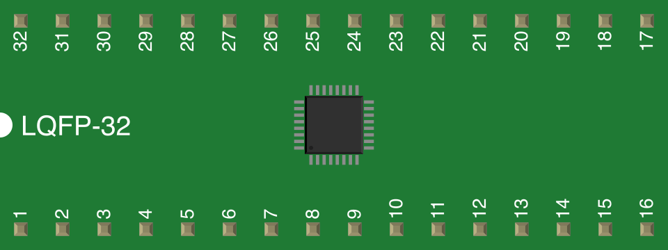
The LQFP-32 (Low-Profile Quad Flat Package) is a surface-mount integrated circuit (IC) package with 32 pins arranged symmetrically on all four sides. This package is designed for compactness, making it ideal for applications where space is a constraint. Its low-profile design ensures efficient thermal performance, making it suitable for high-density circuit boards.
Explore Projects Built with LQFP-32
 Open Project in Cirkit Designer
 Open Project in Cirkit Designer
 Open Project in Cirkit Designer
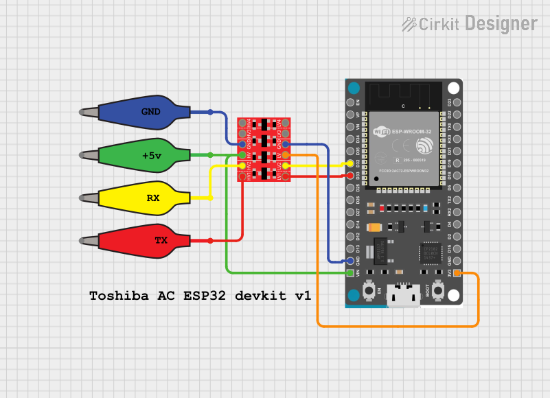 Open Project in Cirkit Designer
Explore Projects Built with LQFP-32
Open Project in Cirkit DesignerOpen Project in Cirkit DesignerOpen Project in Cirkit DesignerOpen Project in Cirkit DesignerCommon Applications and Use Cases
- Microcontrollers and digital signal processors (DSPs)
- Consumer electronics (e.g., smartphones, tablets, and wearables)
- Automotive electronics
- Industrial control systems
- Communication devices
- Embedded systems
Technical Specifications
The following table outlines the key technical specifications of the LQFP-32 package:
| Parameter | Specification |
|---|---|
| Manufacturer | Generic |
| Part ID | LQFP-32 |
| Number of Pins | 32 |
| Package Type | Low-Profile Quad Flat Package (LQFP) |
| Pin Pitch | 0.8 mm |
| Body Size | 7 mm x 7 mm |
| Body Thickness | 1.4 mm (maximum) |
| Thermal Resistance (Junction to Ambient) | ~30°C/W (typical) |
| Mounting Type | Surface Mount Technology (SMT) |
| Operating Temperature Range | -40°C to +125°C |
| Moisture Sensitivity Level | Level 3 (JEDEC J-STD-020) |
Pin Configuration and Descriptions
The LQFP-32 package has 32 pins arranged in a square layout. Below is a general pin configuration table. Note that the specific pin functions depend on the IC housed within the package.
| Pin Number | Description | Typical Function |
|---|---|---|
| 1-8 | General I/O or Power | GPIO, VCC, or GND |
| 9-16 | Signal or Control Lines | Data, Clock, or Reset |
| 17-24 | General I/O or Power | GPIO, VCC, or GND |
| 25-32 | Signal or Control Lines | Data, Clock, or Reset |
Refer to the datasheet of the specific IC for detailed pin assignments.
Usage Instructions
How to Use the LQFP-32 in a Circuit
- PCB Design: Ensure your PCB layout matches the LQFP-32 footprint. The pin pitch is 0.8 mm, so precise alignment is critical.
- Soldering: Use reflow soldering for mounting the LQFP-32 package. Apply solder paste to the PCB pads, place the component, and heat the board using a reflow oven.
- Thermal Management: To optimize thermal performance, include thermal vias under the package if the IC generates significant heat.
- Testing: After soldering, inspect the connections using an X-ray or microscope to ensure no solder bridges or cold joints.
Important Considerations and Best Practices
- Moisture Sensitivity: The LQFP-32 package has a moisture sensitivity level of 3. Store it in a dry environment and bake it before soldering if exposed to moisture for an extended period.
- ESD Protection: Handle the component with proper ESD precautions to avoid damage.
- Alignment: Use a pick-and-place machine for precise alignment during assembly.
- Cleaning: After soldering, clean the PCB to remove flux residues, which can cause corrosion or electrical leakage.
Example: Connecting an LQFP-32 Microcontroller to an Arduino UNO
If the LQFP-32 package houses a microcontroller, you can interface it with an Arduino UNO for programming or communication. Below is an example of connecting an LQFP-32 microcontroller via SPI:
// Example: SPI communication between Arduino UNO and LQFP-32 microcontroller

#include <SPI.h> // Include the SPI library

const int CS_PIN = 10; // Chip Select pin for the LQFP-32 microcontroller

void setup() {
  pinMode(CS_PIN, OUTPUT); // Set the CS pin as an output
  digitalWrite(CS_PIN, HIGH); // Set CS pin to HIGH (inactive)

  SPI.begin(); // Initialize SPI communication
  Serial.begin(9600); // Initialize serial communication for debugging
}

void loop() {
  digitalWrite(CS_PIN, LOW); // Activate the LQFP-32 microcontroller
  SPI.transfer(0x01); // Send a sample command (e.g., 0x01)
  digitalWrite(CS_PIN, HIGH); // Deactivate the LQFP-32 microcontroller

  delay(1000); // Wait for 1 second before sending the next command
}
Note: The specific SPI commands and pin connections depend on the microcontroller housed in the LQFP-32 package. Refer to the microcontroller's datasheet for details.
Troubleshooting and FAQs
Common Issues Users Might Face
- Solder Bridges: Adjacent pins may short due to the small pin pitch.
- Solution: Use a solder wick or desoldering braid to remove excess solder.
- Misalignment: The component may not align perfectly with the PCB pads.
- Solution: Use a pick-and-place machine or manually adjust the alignment before reflow soldering.
- Thermal Issues: The IC may overheat during operation.
- Solution: Add thermal vias and ensure proper heat dissipation through the PCB design.
- Moisture Damage: The package may absorb moisture, leading to defects during soldering.
- Solution: Bake the component at 125°C for 24 hours before soldering if exposed to moisture.
FAQs
Q1: Can I hand-solder an LQFP-32 package?
A1: While possible, hand-soldering an LQFP-32 package is challenging due to the small pin pitch. Use a fine-tipped soldering iron and magnification tools for best results.
Q2: What is the recommended stencil thickness for solder paste application?
A2: A stencil thickness of 0.12 mm to 0.15 mm is recommended for LQFP-32 packages.
Q3: How do I clean flux residue under the package?
A3: Use a no-clean flux or an ultrasonic cleaner with isopropyl alcohol to clean under the package.
Q4: Can I use the LQFP-32 package in high-vibration environments?
A4: Yes, but ensure the PCB design includes proper mechanical support to prevent stress on the solder joints.
This concludes the documentation for the LQFP-32 package. For further details, refer to the datasheet of the specific IC housed in the package.