Cirkit Designer Logo
Cirkit Designer
Your all-in-one circuit design IDE
Home / 
Component Documentation

How to Use LORA E5 Development Kit: Examples, Pinouts, and Specs

Image of LORA E5 Development Kit
Cirkit Designer LogoDesign with LORA E5 Development Kit in Cirkit Designer

Introduction

The LORA E5 Development Kit is a compact and versatile development board designed for LoRa (Long Range) communication. It integrates the LORA-E5 module, which combines a powerful STM32 microcontroller and a Semtech SX126X LoRa transceiver. This development kit is ideal for prototyping IoT applications that require long-range, low-power wireless communication.

Explore Projects Built with LORA E5 Development Kit

Use Cirkit Designer to design, explore, and prototype these projects online. Some projects support real-time simulation. Click "Open Project" to start designing instantly!
ESP32-Based Smart Agriculture System with LoRa Communication
Image of Soil Monitoring Device: A project utilizing LORA E5 Development Kit in a practical application
This circuit features an ESP32 Devkit V1 microcontroller as the central processing unit, interfacing with various sensors including a PH Meter, an NPK Soil Sensor, and a Soil Moisture Sensor for environmental data collection. It also includes an EBYTE LoRa E220 module for wireless communication. Power management is handled by a Step Up Boost Power Converter, which is connected to a 12V Battery, stepping up the voltage to power the ESP32 and sensors, with common ground connections throughout the circuit.
Cirkit Designer LogoOpen Project in Cirkit Designer
ESP32-Based LoRa Communication System with Alert Notifications
Image of Receiver: A project utilizing LORA E5 Development Kit in a practical application
This circuit features an ESP32 Devkit V1 microcontroller interfaced with a LORA_RA02 module for long-range communication and a buzzer module for audio signaling. The ESP32 controls the buzzer and manages the communication via the LORA module. Additionally, there is an LED with a current-limiting resistor connected to the ESP32, likely used for status indication.
Cirkit Designer LogoOpen Project in Cirkit Designer
Arduino UNO and LoRa E220 Wireless Communication Module with Resistor Network
Image of Conexion LoRa: A project utilizing LORA E5 Development Kit in a practical application
This circuit features an Arduino UNO microcontroller interfaced with an EBYTE LoRa E220 module for wireless communication. The circuit includes two resistors for signal conditioning, with one resistor connected to the Arduino's D9 pin and the other forming part of the connection between the LoRa module's RXD pin and ground. The Arduino controls the LoRa module's mode and communication through its digital pins.
Cirkit Designer LogoOpen Project in Cirkit Designer
ESP8266 NodeMCU Wi-Fi Enabled OLED Display with RYLR896 Communication Module
Image of Smart Irrigation system Rx Side: A project utilizing LORA E5 Development Kit in a practical application
This circuit features an ESP8266 NodeMCU microcontroller connected to a 0.96" OLED display and an RYLR896 LoRa module. The ESP8266 communicates with the OLED via I2C protocol and interfaces with the LoRa module using UART, enabling wireless data transmission and display capabilities.
Cirkit Designer LogoOpen Project in Cirkit Designer

Explore Projects Built with LORA E5 Development Kit

Use Cirkit Designer to design, explore, and prototype these projects online. Some projects support real-time simulation. Click "Open Project" to start designing instantly!
Image of Soil Monitoring Device: A project utilizing LORA E5 Development Kit in a practical application
ESP32-Based Smart Agriculture System with LoRa Communication
This circuit features an ESP32 Devkit V1 microcontroller as the central processing unit, interfacing with various sensors including a PH Meter, an NPK Soil Sensor, and a Soil Moisture Sensor for environmental data collection. It also includes an EBYTE LoRa E220 module for wireless communication. Power management is handled by a Step Up Boost Power Converter, which is connected to a 12V Battery, stepping up the voltage to power the ESP32 and sensors, with common ground connections throughout the circuit.
Cirkit Designer LogoOpen Project in Cirkit Designer
Image of Receiver: A project utilizing LORA E5 Development Kit in a practical application
ESP32-Based LoRa Communication System with Alert Notifications
This circuit features an ESP32 Devkit V1 microcontroller interfaced with a LORA_RA02 module for long-range communication and a buzzer module for audio signaling. The ESP32 controls the buzzer and manages the communication via the LORA module. Additionally, there is an LED with a current-limiting resistor connected to the ESP32, likely used for status indication.
Cirkit Designer LogoOpen Project in Cirkit Designer
Image of Conexion LoRa: A project utilizing LORA E5 Development Kit in a practical application
Arduino UNO and LoRa E220 Wireless Communication Module with Resistor Network
This circuit features an Arduino UNO microcontroller interfaced with an EBYTE LoRa E220 module for wireless communication. The circuit includes two resistors for signal conditioning, with one resistor connected to the Arduino's D9 pin and the other forming part of the connection between the LoRa module's RXD pin and ground. The Arduino controls the LoRa module's mode and communication through its digital pins.
Cirkit Designer LogoOpen Project in Cirkit Designer
Image of Smart Irrigation system Rx Side: A project utilizing LORA E5 Development Kit in a practical application
ESP8266 NodeMCU Wi-Fi Enabled OLED Display with RYLR896 Communication Module
This circuit features an ESP8266 NodeMCU microcontroller connected to a 0.96" OLED display and an RYLR896 LoRa module. The ESP8266 communicates with the OLED via I2C protocol and interfaces with the LoRa module using UART, enabling wireless data transmission and display capabilities.
Cirkit Designer LogoOpen Project in Cirkit Designer

Common Applications and Use Cases

  • Smart agriculture (e.g., soil moisture monitoring, weather stations)
  • Industrial IoT (e.g., asset tracking, predictive maintenance)
  • Smart cities (e.g., parking sensors, environmental monitoring)
  • Home automation and security systems
  • Remote data logging and telemetry

Technical Specifications

Key Technical Details

  • Microcontroller: STM32WLE5JC (ARM Cortex-M4, 48 MHz)
  • LoRa Transceiver: Semtech SX126X
  • Frequency Bands: 150 MHz to 960 MHz (supports global ISM bands)
  • Communication Protocols: LoRaWAN, FSK, GFSK, BPSK
  • Operating Voltage: 3.3V
  • Power Consumption:
    • Sleep mode: < 2 µA
    • Transmit mode: Up to 22 dBm (160 mA max)
  • Interfaces: UART, I2C, SPI, GPIO, ADC
  • Antenna Connector: IPEX (external antenna required)
  • Dimensions: 24 mm x 24 mm

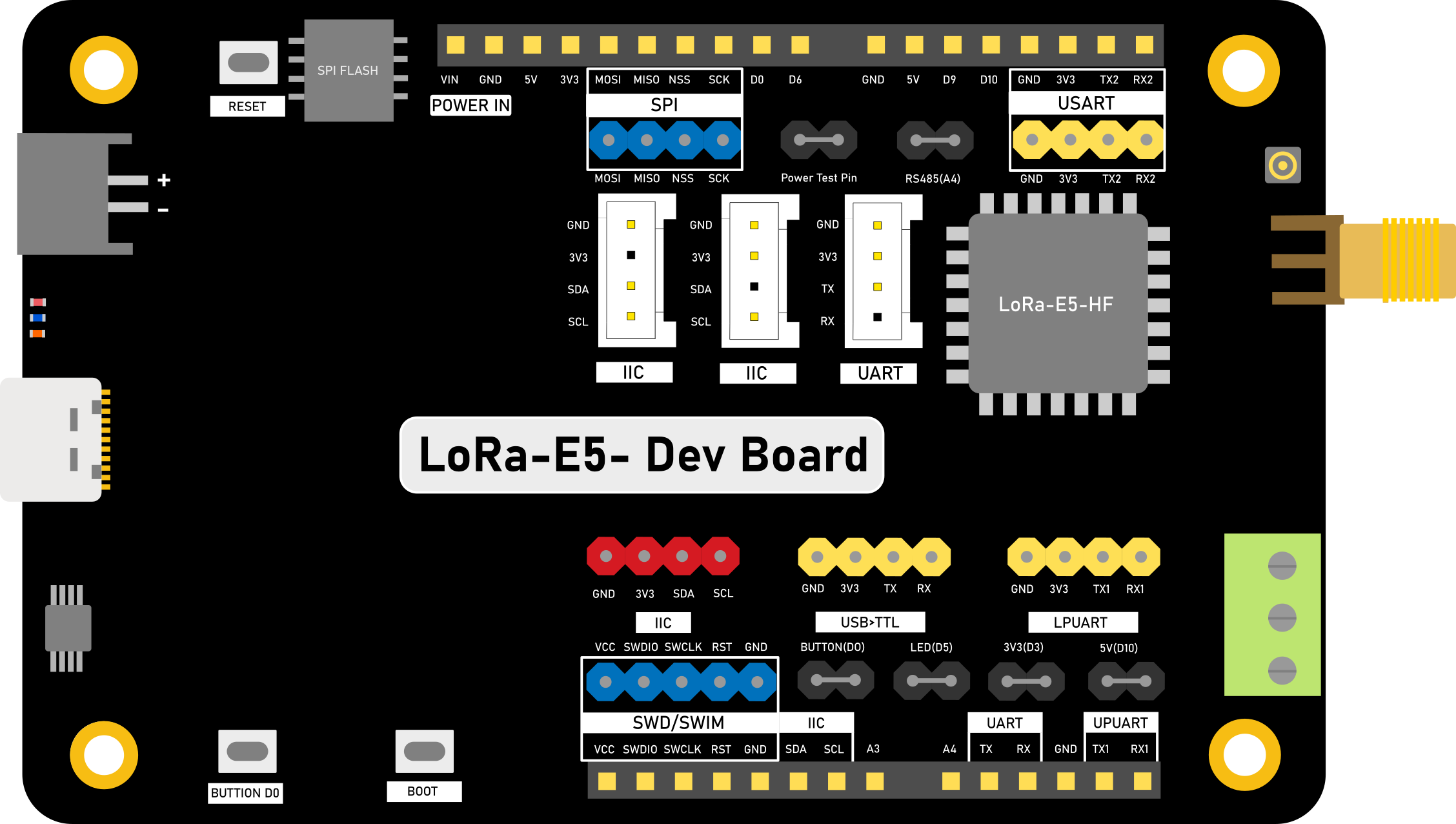
Pin Configuration and Descriptions

The LORA E5 Development Kit features a 24-pin header for easy prototyping. Below is the pinout description:

Pin Number Pin Name Description
1 VCC 3.3V Power Supply
2 GND Ground
3 UART_TX UART Transmit
4 UART_RX UART Receive
5 I2C_SCL I2C Clock Line
6 I2C_SDA I2C Data Line
7 SPI_SCK SPI Clock
8 SPI_MISO SPI Master In, Slave Out
9 SPI_MOSI SPI Master Out, Slave In
10 SPI_CS SPI Chip Select
11 GPIO1 General Purpose I/O
12 GPIO2 General Purpose I/O
13 ADC1 Analog-to-Digital Converter Input
14 ADC2 Analog-to-Digital Converter Input
15 RESET Reset Pin
16 BOOT Boot Mode Selection
17 RF_OUT RF Output for Antenna
18-24 NC Not Connected

Usage Instructions

How to Use the LORA E5 Development Kit in a Circuit

  1. Power the Board: Connect the VCC pin to a 3.3V power source and GND to ground.
  2. Connect the Antenna: Attach an external antenna to the IPEX connector for proper RF performance.
  3. Interface with a Microcontroller: Use UART, I2C, or SPI to communicate with the LORA E5 module.
  4. Program the Module: Use AT commands or custom firmware to configure the LoRa settings (e.g., frequency, spreading factor, power).
  5. Deploy the Circuit: Integrate the development kit into your IoT application and test the communication range.

Important Considerations and Best Practices

  • Antenna Placement: Ensure the antenna is placed away from metal objects and other RF sources to avoid interference.
  • Power Supply: Use a stable 3.3V power source to prevent communication issues.
  • Firmware Updates: Regularly update the firmware to access the latest features and bug fixes.
  • Regulatory Compliance: Verify that your application complies with local regulations for LoRa frequency bands and power levels.

Example: Connecting to an Arduino UNO

The LORA E5 Development Kit can be connected to an Arduino UNO via UART. Below is an example of Arduino code to send AT commands to the module:

#include <SoftwareSerial.h>

// Define RX and TX pins for SoftwareSerial
SoftwareSerial loraSerial(10, 11); // RX = Pin 10, TX = Pin 11

void setup() {
  // Initialize serial communication with the LORA E5 module
  loraSerial.begin(9600); // Default baud rate for LORA E5
  Serial.begin(9600);     // Serial monitor for debugging

  // Send an AT command to check communication
  loraSerial.println("AT");
  Serial.println("Sent: AT");
}

void loop() {
  // Check for responses from the LORA E5 module
  if (loraSerial.available()) {
    String response = loraSerial.readString();
    Serial.println("Received: " + response);
  }

  // Add a delay to avoid flooding the serial monitor
  delay(1000);
}

Troubleshooting and FAQs

Common Issues and Solutions

  1. No Response to AT Commands

    • Cause: Incorrect baud rate or wiring.
    • Solution: Verify the UART connections and ensure the baud rate is set to 9600.
  2. Poor Communication Range

    • Cause: Improper antenna placement or low transmission power.
    • Solution: Check the antenna connection and ensure the transmission power is configured correctly.
  3. Module Not Powering On

    • Cause: Insufficient power supply.
    • Solution: Ensure the VCC pin is receiving a stable 3.3V supply.
  4. Interference with Other Devices

    • Cause: Overlapping frequency bands.
    • Solution: Configure the module to use a different frequency within the allowed range.

FAQs

  • Q: Can I use the LORA E5 Development Kit with a 5V microcontroller?

    • A: Yes, but you must use a level shifter to convert 5V signals to 3.3V.
  • Q: What is the maximum range of the LORA E5 Development Kit?

    • A: The range depends on environmental factors but can reach up to 10 km in open areas.
  • Q: How do I update the firmware?

    • A: Use the STM32CubeProgrammer tool to flash the latest firmware via the UART interface.
  • Q: Can I use the LORA E5 Development Kit for LoRaWAN applications?

    • A: Yes, the module supports LoRaWAN and can be configured using AT commands or custom firmware.

This documentation provides a comprehensive guide to using the LORA E5 Development Kit for your IoT projects. Happy prototyping!