How to Use Driver: Examples, Pinouts, and Specs
Introduction
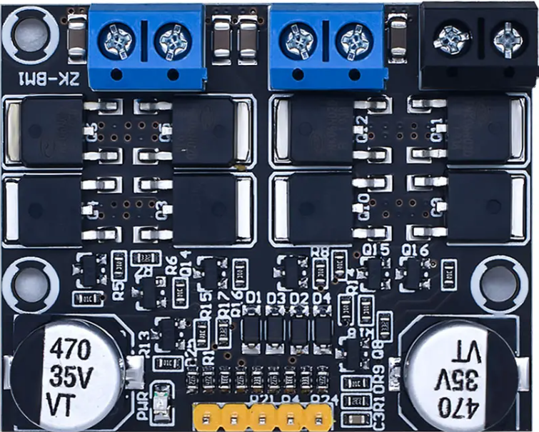
The WAVGAT Driver Module is an electronic component designed to control and regulate power to other components within a circuit. It is commonly used in applications that require precise control over the operation of motors, LEDs, and other high-power devices. The driver module ensures that these components receive the correct amount of power for optimal performance, while also providing protection against overcurrent and overheating.
Explore Projects Built with Driver
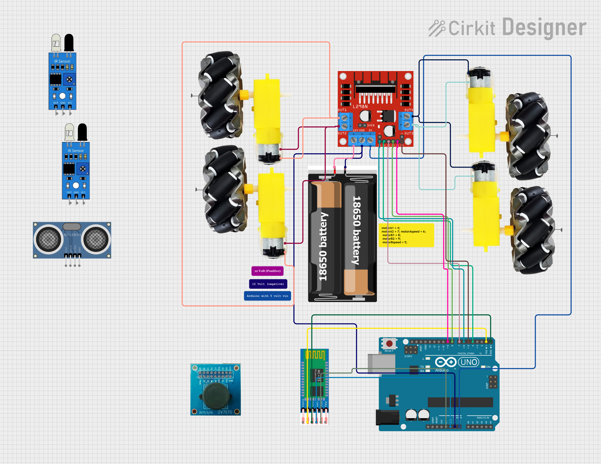
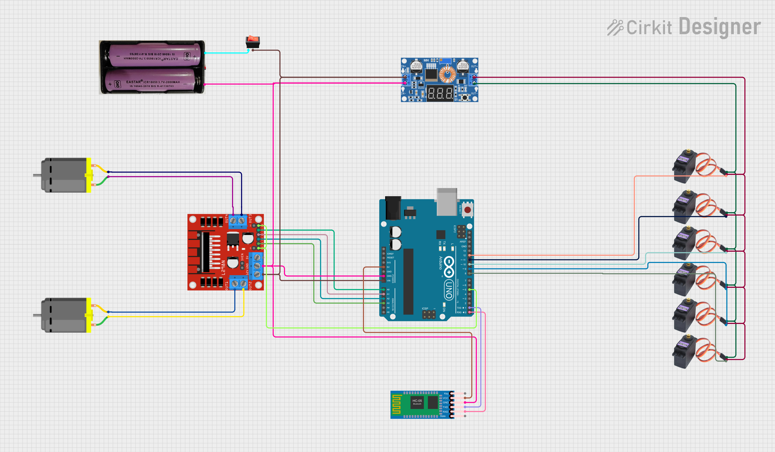
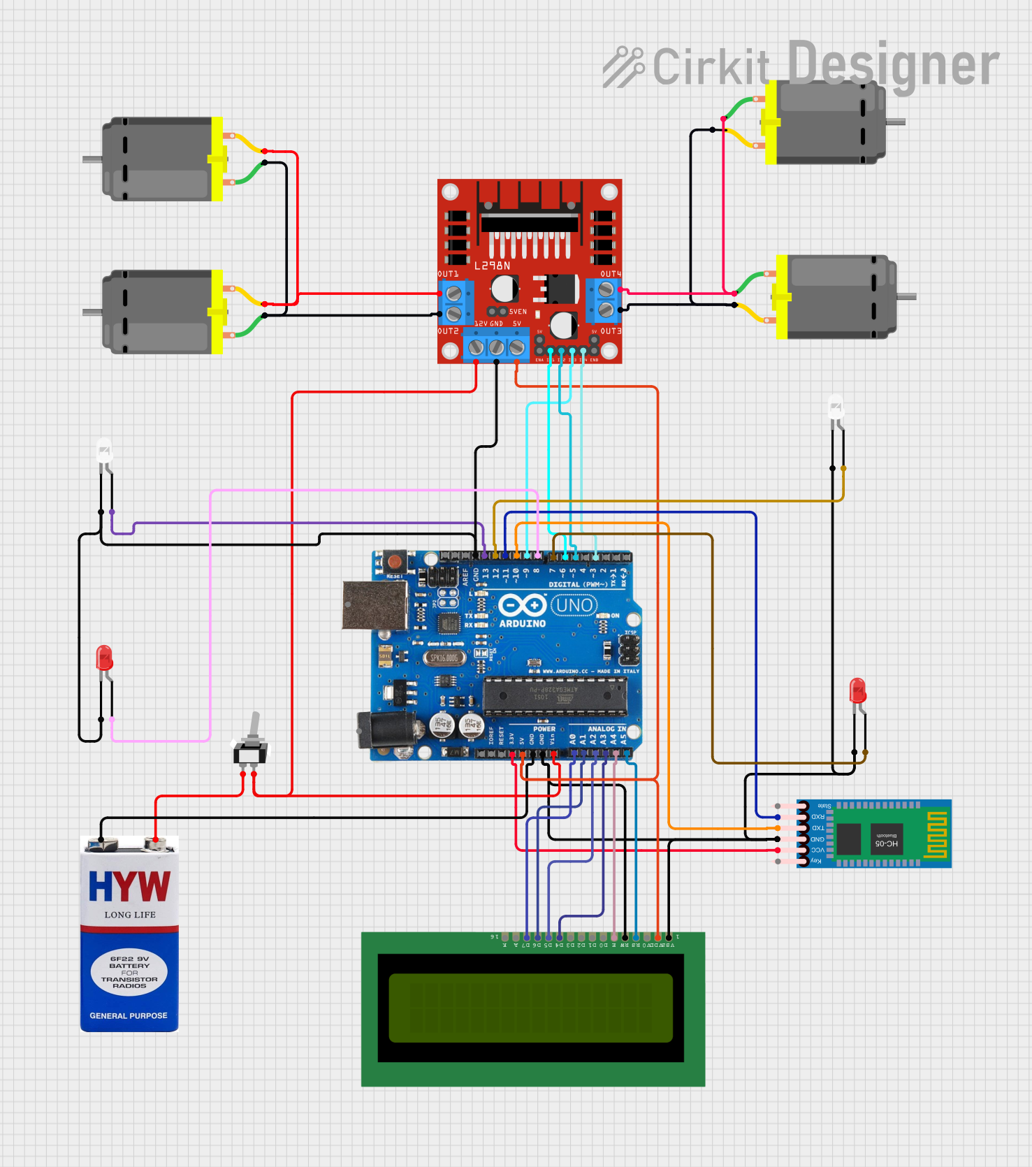
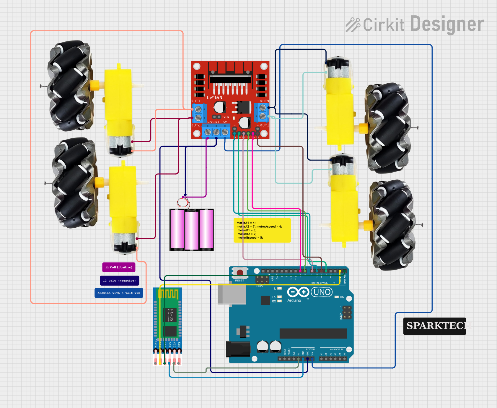
Explore Projects Built with Driver
Common Applications and Use Cases
- Motor control in robotics and automation systems
- LED dimming and control in lighting systems
- Power regulation for sensitive electronic circuits
Technical Specifications
Key Technical Details
- Input Voltage Range: 3.3V to 5V
- Output Current: Up to 2A (peak)
- Operating Temperature: -40°C to +85°C
Pin Configuration and Descriptions
| Pin Number | Name | Description |
|---|---|---|
| 1 | Vcc | Power supply input (3.3V to 5V) |
| 2 | GND | Ground connection |
| 3 | IN | Input signal to control the driver |
| 4 | OUT | Output to the controlled component |
Usage Instructions
How to Use the Component in a Circuit
- Power Supply Connection: Connect the Vcc pin to a suitable power supply within the specified voltage range. Ensure that the power supply can deliver sufficient current for the load.
- Ground Connection: Connect the GND pin to the ground of your power supply and the ground of the control circuit (e.g., Arduino UNO).
- Input Signal: Connect the IN pin to a control signal source, such as a PWM output from a microcontroller.
- Output Connection: Connect the OUT pin to the component you wish to drive, such as a motor or LED.
Important Considerations and Best Practices
- Always verify that the power supply voltage and current capabilities are within the specifications of the driver module.
- Use a flyback diode when driving inductive loads like motors to prevent voltage spikes.
- Ensure adequate heat dissipation for the driver module when operating at high currents.
- Avoid running the driver at its maximum ratings for extended periods to prolong its lifespan.
Example Code for Arduino UNO
// Example code to control a motor with the WAVGAT Driver Module
#define DRIVER_IN_PIN 3 // Connect to the IN pin of the driver

void setup() {
  pinMode(DRIVER_IN_PIN, OUTPUT);
}

void loop() {
  // Spin the motor at full speed for 2 seconds
  analogWrite(DRIVER_IN_PIN, 255); // Send a full-speed PWM signal
  delay(2000);

  // Stop the motor for 2 seconds
  analogWrite(DRIVER_IN_PIN, 0); // Send a zero-speed PWM signal
  delay(2000);

  // Spin the motor at half speed for 2 seconds
  analogWrite(DRIVER_IN_PIN, 127); // Send a half-speed PWM signal
  delay(2000);
}
Troubleshooting and FAQs
Common Issues Users Might Face
- Motor not spinning: Ensure that the power supply is correctly connected and that the input signal is being sent from the microcontroller.
- Overheating: If the driver module is overheating, check if the current draw is within the specified limit and improve heat dissipation.
- Inconsistent operation: Verify that all connections are secure and that there is no interference with the input signal.
Solutions and Tips for Troubleshooting
- Double-check wiring and solder joints for any loose connections or shorts.
- Use a multimeter to measure the voltage at the Vcc and GND pins to ensure proper power supply.
- If using PWM, verify the frequency and duty cycle are within the driver's operating range.
FAQs
Q: Can I use this driver module with a 3.3V microcontroller? A: Yes, the driver module can operate with a 3.3V input signal.
Q: What is the maximum frequency for the PWM input signal? A: The maximum recommended frequency for the PWM input signal is 100kHz.
Q: How can I increase the current handling capability of the driver? A: To handle higher currents, consider using a heatsink or a fan for cooling, or use multiple drivers in parallel, ensuring that the load is evenly distributed.