How to Use Closed Loop Stepper: Examples, Pinouts, and Specs

Introduction
A Closed Loop Stepper Motor is an advanced type of stepper motor that integrates a feedback system, usually in the form of an encoder, to continuously monitor the position of the motor shaft. This feedback allows the motor control system to adjust the current and phase alignment, ensuring the motor's position is as intended, even under varying load conditions. Closed Loop Steppers are known for their high performance, precision, and reliability, making them ideal for applications requiring exact positioning and error correction capabilities, such as CNC machines, 3D printers, robotics, and high-speed automation equipment.
Explore Projects Built with Closed Loop Stepper
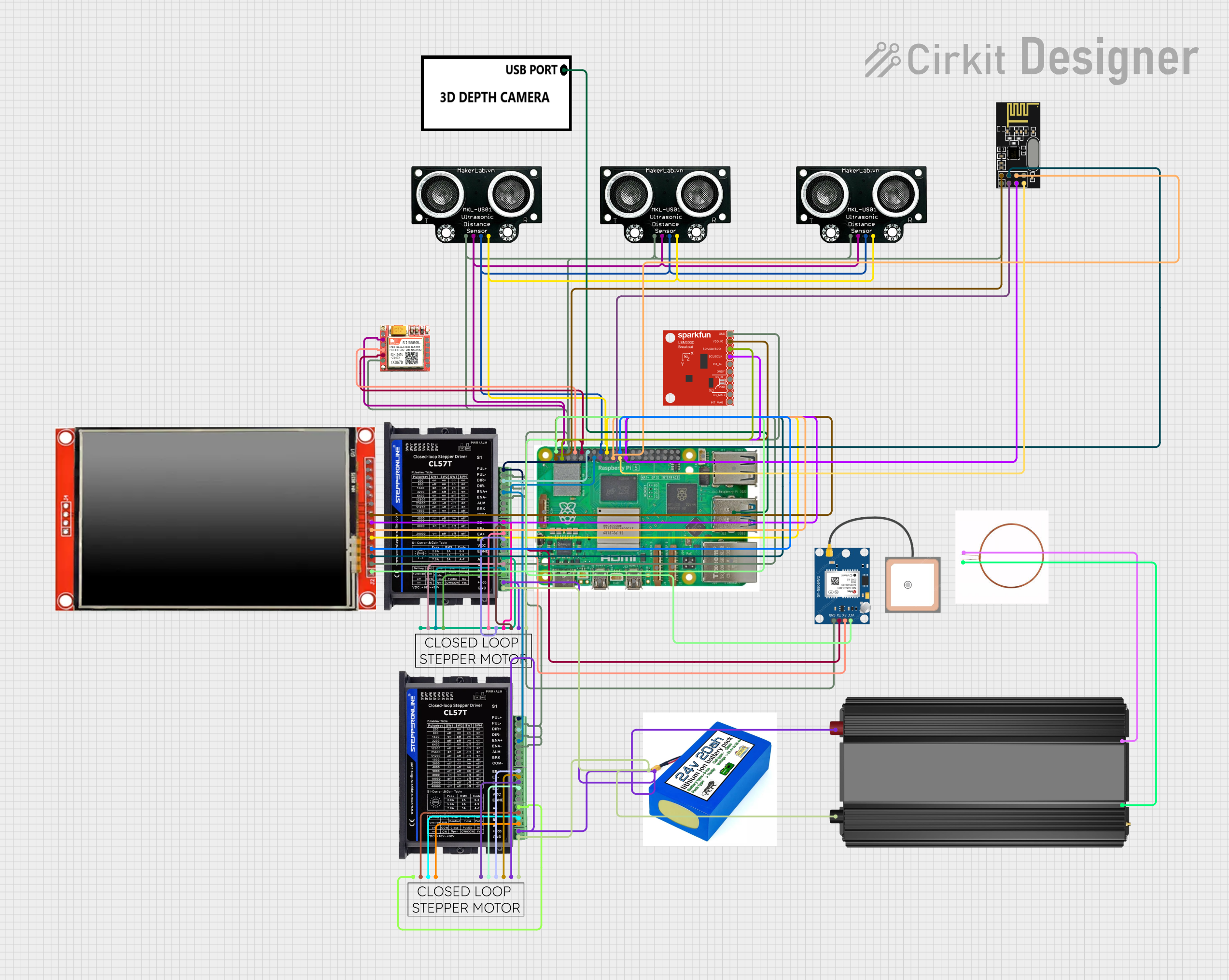
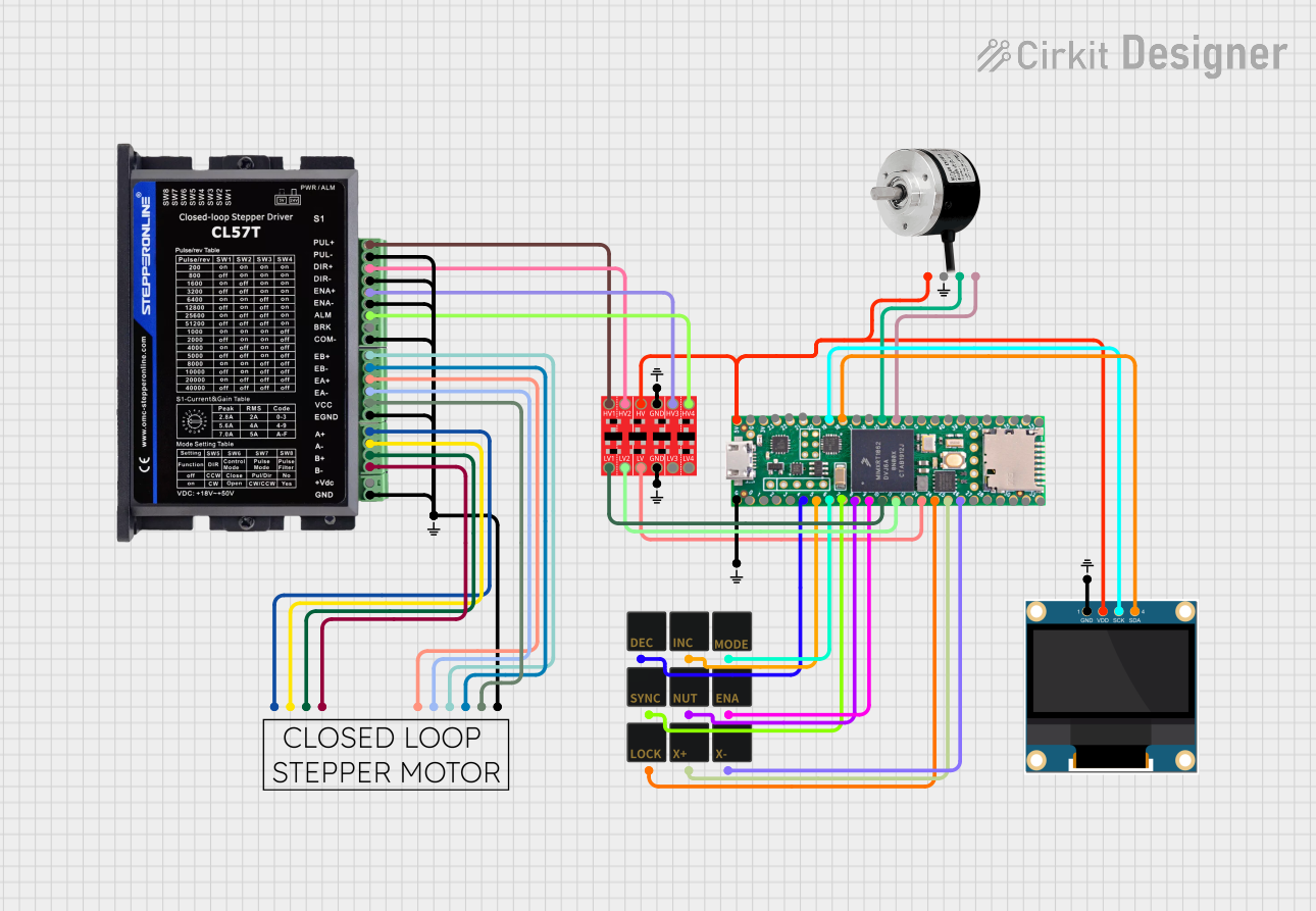
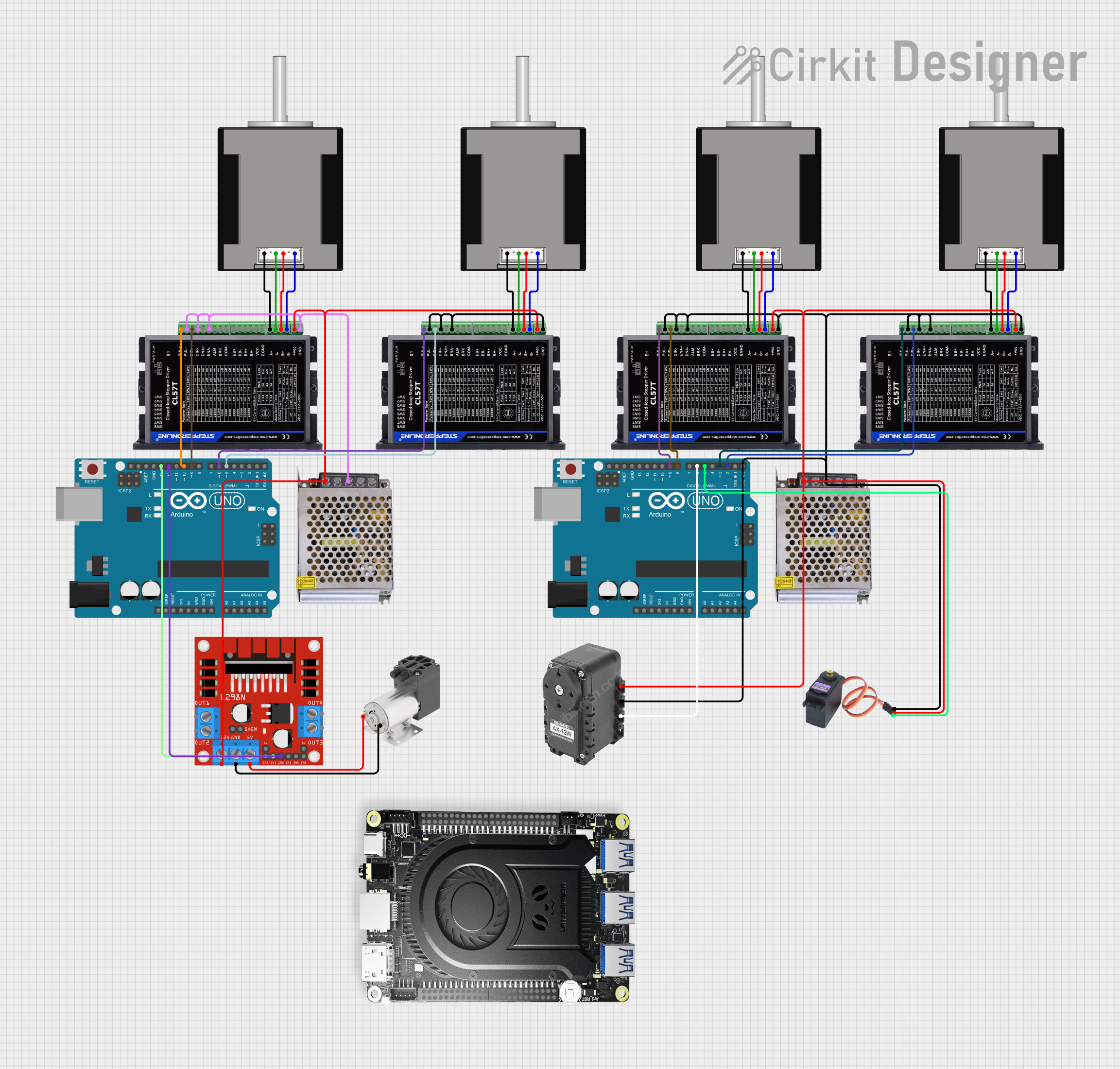
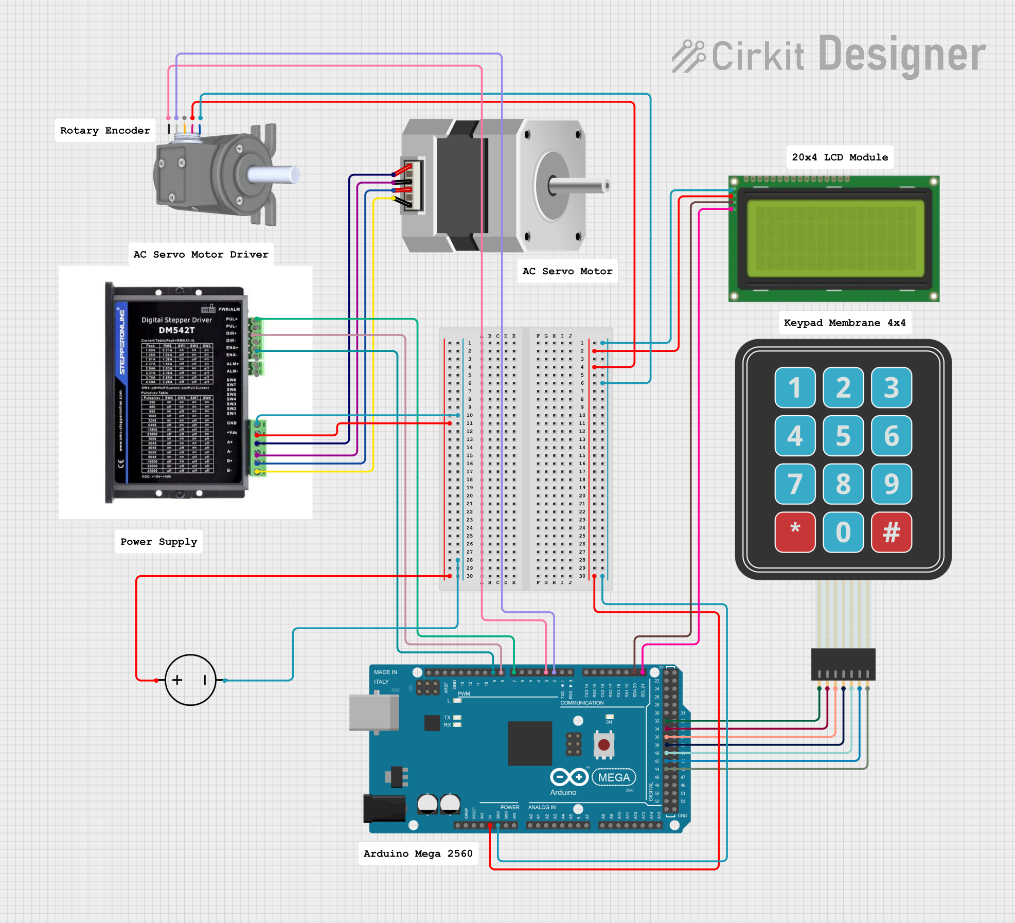
Explore Projects Built with Closed Loop Stepper
Technical Specifications
General Characteristics
- Step Angle: Typically 1.8 degrees per step (200 steps per revolution)
- Rated Voltage: Varies by model (e.g., 24V, 48V)
- Rated Current: Varies by model (e.g., 2A, 4A per phase)
- Holding Torque: Varies by model (e.g., 1Nm, 3Nm)
- Rotor Inertia: Specified by model
- Encoder Resolution: Varies by model (e.g., 1000 counts per revolution)
Pin Configuration and Descriptions
| Pin Number | Description | Notes |
|---|---|---|
| 1 | A+ (Phase A) | Connect to motor driver phase A+ |
| 2 | A- (Phase A) | Connect to motor driver phase A- |
| 3 | B+ (Phase B) | Connect to motor driver phase B+ |
| 4 | B- (Phase B) | Connect to motor driver phase B- |
| 5 | Encoder Vcc | Power supply for the encoder |
| 6 | Encoder GND | Ground for the encoder |
| 7 | Encoder A Output | Encoder channel A signal output |
| 8 | Encoder B Output | Encoder channel B signal output |
| 9 | Encoder Index Output | Optional, for homing reference |
Usage Instructions
Integration into a Circuit
- Power Supply: Ensure that the power supply matches the voltage and current requirements of the Closed Loop Stepper Motor.
- Motor Driver: Connect the motor phases (A+ A- B+ B-) to a compatible stepper motor driver capable of closed-loop control.
- Encoder Feedback: Connect the encoder outputs (Vcc, GND, A Output, B Output) to the motor driver or controller to provide feedback.
- Controller Setup: Configure the controller to use the feedback from the encoder to adjust the motor's position as needed.
Best Practices
- Heat Management: Ensure adequate cooling for the motor and driver, as closed-loop operation can generate significant heat.
- Cable Shielding: Use shielded cables for encoder signals to prevent electromagnetic interference.
- Proper Grounding: Ground the motor, driver, and control system properly to avoid electrical noise and potential damage.
- Software Configuration: Calibrate the system and set appropriate parameters for acceleration, deceleration, and current limits.
Troubleshooting and FAQs
Common Issues
- Motor Stalling or Skipping Steps: Check for mechanical obstructions, ensure the motor is not overloaded, and verify that the power supply is adequate.
- Encoder Signal Noise: Ensure that encoder cables are shielded and connections are secure. Check for proper grounding.
- Inaccurate Positioning: Calibrate the encoder and verify that the encoder resolution is set correctly in the controller software.
FAQs
Q: Can I use a Closed Loop Stepper Motor without an encoder? A: No, the encoder is essential for the closed-loop control system to function correctly.
Q: What happens if the encoder fails? A: The motor may lose its position accuracy and could behave unpredictably. It's important to have error-detection mechanisms in place.
Q: How do I choose the right Closed Loop Stepper Motor for my application? A: Consider the required torque, speed, voltage, current, and the precision needed for your application.
Example Arduino Code
Below is an example of Arduino code to control a Closed Loop Stepper Motor using a compatible stepper motor driver. This example assumes the use of a library that supports closed-loop control.
#include <ClosedLoopStepper.h>

ClosedLoopStepper stepper;

void setup() {
  // Initialize the stepper with the pin numbers connected to the driver
  stepper.begin(2, 3, 4, 5); // Pins for A+, A-, B+, B-
  stepper.setEncoderPins(6, 7); // Pins for Encoder A and B outputs
  stepper.setResolution(1000); // Set encoder resolution (counts per revolution)
}

void loop() {
  // Move the stepper to a new position with closed-loop control
  stepper.moveTo(200); // Move 200 steps from the current position
  delay(1000); // Wait for 1 second

  // You can add more motion commands and logic as needed
}
Note: The actual implementation will vary depending on the specific hardware and library used. Always refer to the manufacturer's datasheet and the library documentation for accurate information and instructions.