How to Use TJA1021: Examples, Pinouts, and Specs
Introduction
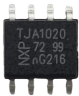
The TJA1021 is a high-speed CAN (Controller Area Network) transceiver manufactured by NXP. It is designed for automotive applications, enabling robust and reliable communication between microcontrollers and CAN networks. The TJA1021 is compliant with ISO 11898-2 and ISO 11898-5 standards, making it suitable for a wide range of automotive and industrial use cases.
Explore Projects Built with TJA1021


Explore Projects Built with TJA1021
Common Applications
- Automotive in-vehicle networking (e.g., engine control, body control modules)
- Industrial automation systems
- Electric vehicle (EV) battery management systems
- Diagnostic tools and equipment
- Communication between embedded systems in harsh environments
Technical Specifications
Key Technical Details
| Parameter | Value |
|---|---|
| Supply Voltage (Vcc) | 4.5 V to 5.5 V |
| Data Rate | Up to 1 Mbps |
| Operating Temperature | -40°C to +125°C |
| Bus Voltage Range | -27 V to +40 V |
| Standby Current | < 10 µA |
| ESD Protection | ±6 kV (HBM) |
| Compliance Standards | ISO 11898-2, ISO 11898-5 |
Pin Configuration and Descriptions
The TJA1021 is available in an 8-pin SO8 package. Below is the pinout and description:
| Pin No. | Pin Name | Description |
|---|---|---|
| 1 | TXD | Transmit Data Input (from microcontroller) |
| 2 | GND | Ground |
| 3 | VCC | Supply Voltage (4.5 V to 5.5 V) |
| 4 | RXD | Receive Data Output (to microcontroller) |
| 5 | STB | Standby Mode Control Input |
| 6 | CANH | High-Level CAN Bus Line |
| 7 | CANL | Low-Level CAN Bus Line |
| 8 | n.c. | Not Connected |
Usage Instructions
How to Use the TJA1021 in a Circuit
- Power Supply: Connect the VCC pin to a regulated 5 V power supply and the GND pin to the ground.
- CAN Bus Lines: Connect the CANH and CANL pins to the respective high and low lines of the CAN bus.
- Microcontroller Interface:
- Connect the TXD pin to the microcontroller's CAN transmit pin.
- Connect the RXD pin to the microcontroller's CAN receive pin.
- Standby Mode: Use the STB pin to control the transceiver's operating mode:
- Logic HIGH: Standby mode (low power consumption).
- Logic LOW: Normal mode (active communication).
- Termination Resistor: Ensure a 120 Ω termination resistor is placed across the CANH and CANL lines at each end of the bus for proper signal integrity.
Important Considerations and Best Practices
- Power Supply Stability: Use decoupling capacitors (e.g., 100 nF and 10 µF) close to the VCC pin to ensure stable operation.
- ESD Protection: While the TJA1021 has built-in ESD protection, additional external protection (e.g., TVS diodes) is recommended for harsh environments.
- Bus Length and Data Rate: Ensure the bus length and data rate comply with CAN specifications to avoid signal degradation.
- Standby Mode: Use the standby mode to reduce power consumption when the transceiver is not actively communicating.
Example Code for Arduino UNO
Below is an example of how to interface the TJA1021 with an Arduino UNO for basic CAN communication:
#include <SPI.h>
#include <mcp_can.h> // Include the MCP_CAN library for CAN communication

// Define the SPI CS pin for the MCP2515 CAN controller
#define CAN_CS_PIN 10

// Initialize the CAN object
MCP_CAN CAN(CAN_CS_PIN);

void setup() {
  Serial.begin(9600); // Initialize serial communication for debugging
  while (!Serial);

  // Initialize the CAN bus at 500 kbps
  if (CAN.begin(MCP_ANY, CAN_500KBPS, MCP_8MHZ) == CAN_OK) {
    Serial.println("CAN bus initialized successfully!");
  } else {
    Serial.println("Error initializing CAN bus.");
    while (1);
  }

  CAN.setMode(MCP_NORMAL); // Set CAN controller to normal mode
  Serial.println("CAN controller set to normal mode.");
}

void loop() {
  // Example: Send a CAN message with ID 0x100 and 8 bytes of data
  byte data[8] = {0x01, 0x02, 0x03, 0x04, 0x05, 0x06, 0x07, 0x08};

  if (CAN.sendMsgBuf(0x100, 0, 8, data) == CAN_OK) {
    Serial.println("Message sent successfully!");
  } else {
    Serial.println("Error sending message.");
  }

  delay(1000); // Wait 1 second before sending the next message
}
Note: The TJA1021 is a transceiver and requires a CAN controller (e.g., MCP2515) to handle the CAN protocol. The above example assumes the use of an MCP2515 CAN controller module.
Troubleshooting and FAQs
Common Issues
No Communication on the CAN Bus:
- Cause: Incorrect wiring or missing termination resistors.
- Solution: Verify all connections and ensure 120 Ω resistors are present at both ends of the CAN bus.
High Standby Current:
- Cause: STB pin not set to HIGH for standby mode.
- Solution: Ensure the STB pin is driven HIGH when the transceiver is not in use.
Data Corruption or Loss:
- Cause: Excessive bus length or noise interference.
- Solution: Reduce the bus length or add shielding to the CAN lines.
Overheating:
- Cause: Overvoltage or excessive current on the CANH/CANL lines.
- Solution: Check the bus voltage and ensure it is within the specified range (-27 V to +40 V).
FAQs
Q1: Can the TJA1021 operate at 3.3 V?
A1: No, the TJA1021 requires a supply voltage between 4.5 V and 5.5 V. Use a level shifter if interfacing with a 3.3 V microcontroller.
Q2: Is the TJA1021 compatible with non-automotive CAN networks?
A2: Yes, the TJA1021 can be used in any CAN network that complies with ISO 11898-2 or ISO 11898-5 standards.
Q3: How do I detect bus errors?
A3: The TJA1021 itself does not handle error detection. Use a CAN controller (e.g., MCP2515) to monitor and handle bus errors.
Q4: Can I use the TJA1021 for single-wire CAN?
A4: No, the TJA1021 is designed for high-speed two-wire CAN networks. Use a single-wire CAN transceiver for such applications.