How to Use ir sensor : Examples, Pinouts, and Specs
Introduction
An infrared (IR) sensor detects infrared radiation, typically emitted by objects as heat. It is a versatile electronic component widely used in various applications, including motion detection, proximity sensing, and remote control systems. IR sensors are integral to devices such as automatic doors, burglar alarms, and line-following robots. They are valued for their ability to detect objects without physical contact, making them ideal for automation and robotics.
Explore Projects Built with ir sensor
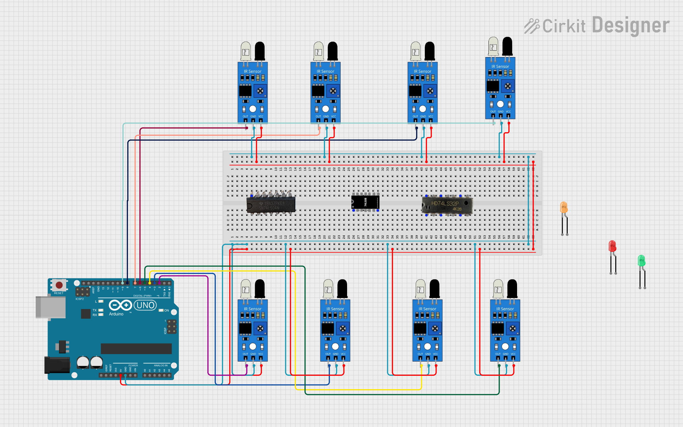
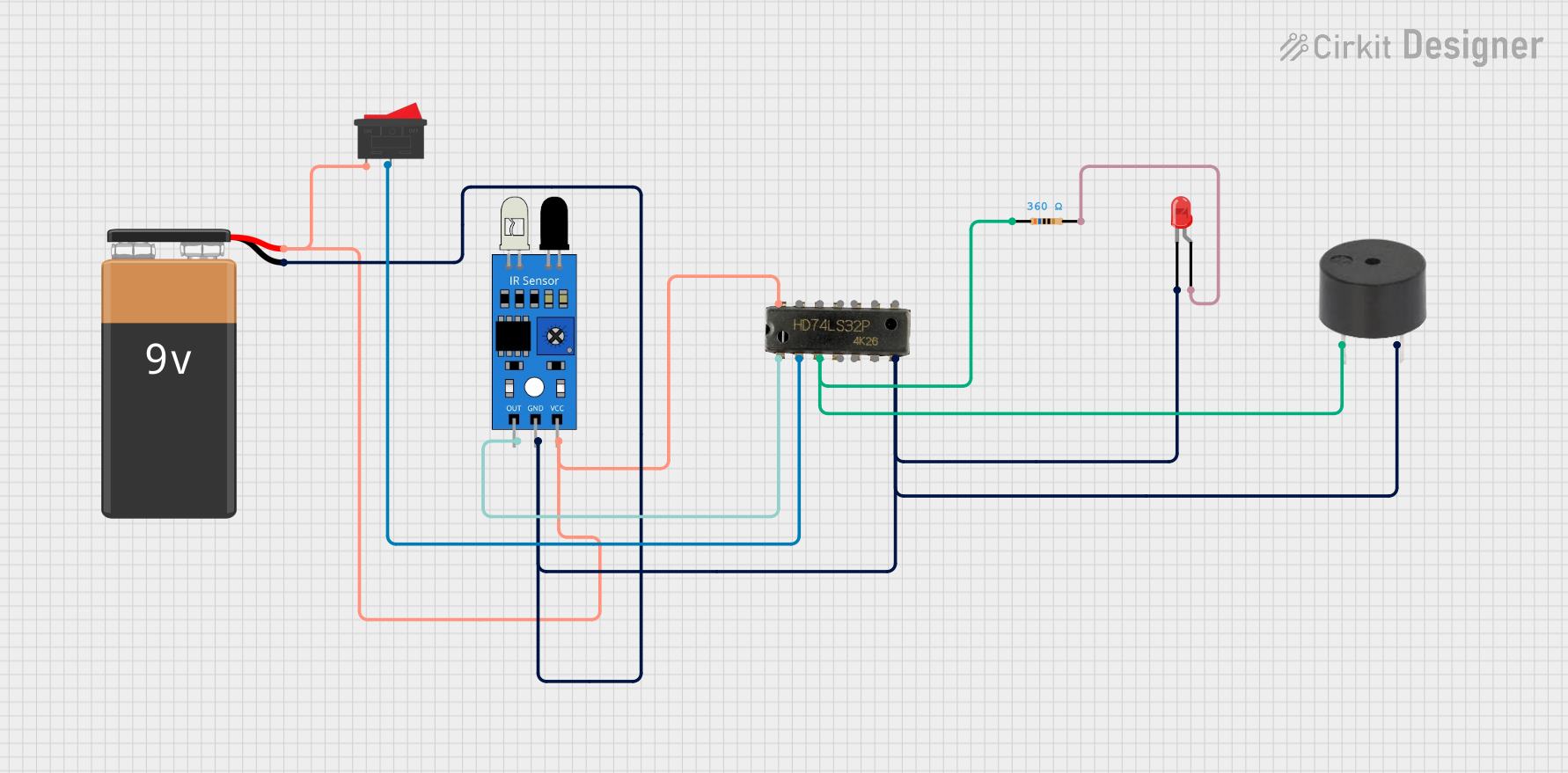
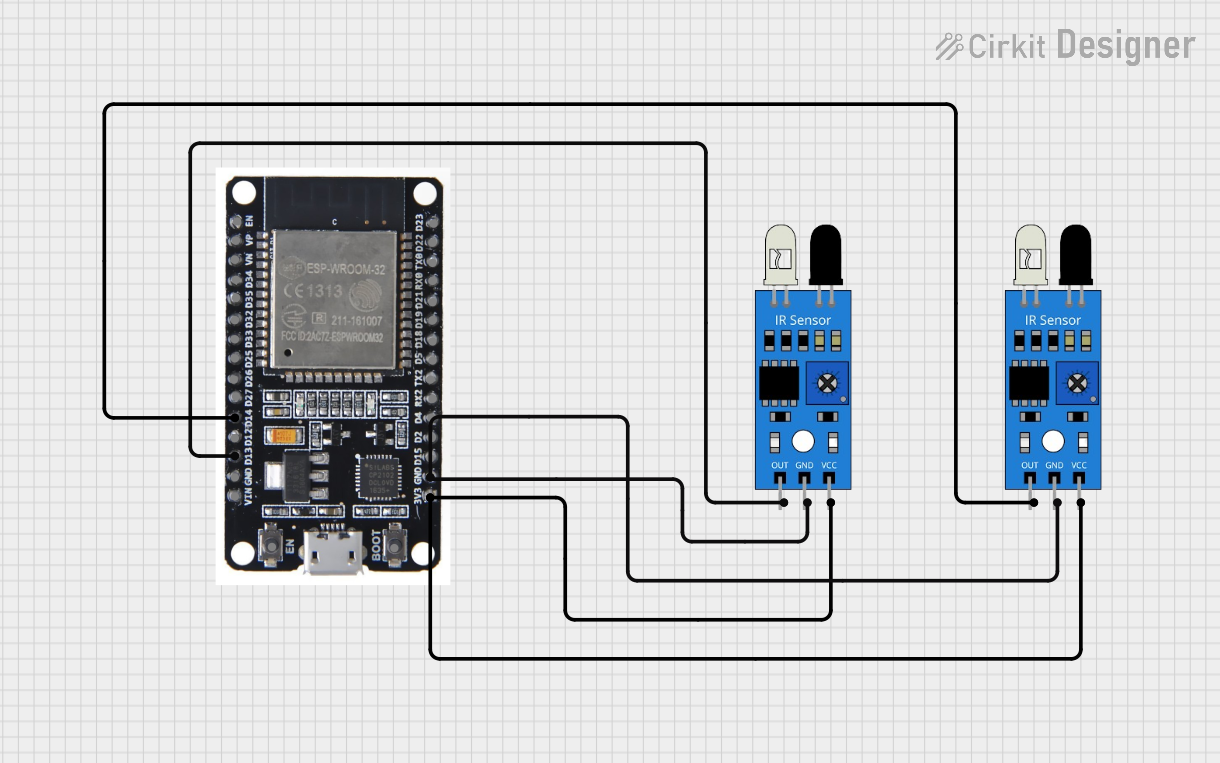
Explore Projects Built with ir sensor
Technical Specifications
Below are the key technical details of a typical IR sensor module:
- Operating Voltage: 3.3V to 5V DC
- Current Consumption: 20mA (typical)
- Detection Range: 2 cm to 30 cm (varies by model)
- Output Type: Digital (High/Low) or Analog (depending on the model)
- Wavelength: 760 nm to 1100 nm (infrared spectrum)
- Response Time: < 2 ms
- Operating Temperature: -25°C to 85°C
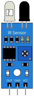
Pin Configuration and Descriptions
The IR sensor module typically has three or more pins. Below is a table describing the common pin configuration:
| Pin Name | Description |
|---|---|
| VCC | Power supply pin (3.3V to 5V DC) |
| GND | Ground pin |
| OUT | Output pin (Digital or Analog signal) |
| EN (optional) | Enable pin to activate/deactivate sensor |
Some advanced IR sensors may include additional pins for sensitivity adjustment or mode selection.
Usage Instructions
How to Use the IR Sensor in a Circuit
- Power the Sensor: Connect the VCC pin to a 3.3V or 5V power source and the GND pin to the ground.
- Connect the Output: Attach the OUT pin to a microcontroller's input pin (e.g., Arduino) or directly to an external circuit.
- Adjust Sensitivity: If the sensor has a potentiometer, adjust it to set the detection range.
- Test the Sensor: Place an object within the detection range and observe the output signal. The OUT pin typically goes HIGH when an object is detected.
Important Considerations and Best Practices
- Avoid Direct Sunlight: IR sensors can be affected by strong ambient light, such as direct sunlight. Use them in controlled lighting conditions for accurate results.
- Maintain Proper Distance: Ensure the object is within the sensor's specified detection range for reliable operation.
- Use Pull-Up Resistors: For digital output sensors, consider using a pull-up resistor to stabilize the signal.
- Shield from Interference: Avoid placing the sensor near other IR-emitting devices to prevent interference.
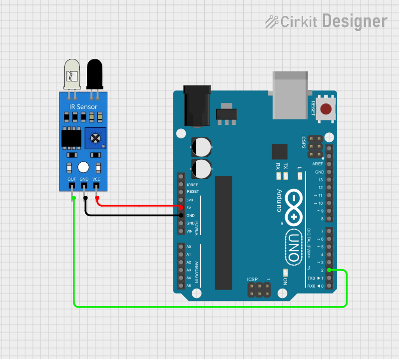
Example: Connecting an IR Sensor to an Arduino UNO
Below is an example of how to connect and use an IR sensor with an Arduino UNO:
Circuit Connections
- Connect the VCC pin of the IR sensor to the 5V pin on the Arduino.
- Connect the GND pin of the IR sensor to the GND pin on the Arduino.
- Connect the OUT pin of the IR sensor to digital pin 2 on the Arduino.
Arduino Code
// IR Sensor Example Code for Arduino UNO
// This code reads the digital output of the IR sensor and turns on an LED
// when an object is detected.

const int irSensorPin = 2;  // IR sensor output pin connected to digital pin 2
const int ledPin = 13;      // Onboard LED pin

void setup() {
  pinMode(irSensorPin, INPUT);  // Set IR sensor pin as input
  pinMode(ledPin, OUTPUT);      // Set LED pin as output
  Serial.begin(9600);           // Initialize serial communication
}

void loop() {
  int sensorValue = digitalRead(irSensorPin);  // Read the IR sensor output

  if (sensorValue == HIGH) {
    // Object detected
    digitalWrite(ledPin, HIGH);  // Turn on the LED
    Serial.println("Object detected!");
  } else {
    // No object detected
    digitalWrite(ledPin, LOW);   // Turn off the LED
    Serial.println("No object detected.");
  }

  delay(100);  // Small delay for stability
}
Troubleshooting and FAQs
Common Issues and Solutions
Sensor Not Detecting Objects
- Cause: Object is outside the detection range.
- Solution: Adjust the sensor's position or sensitivity (if adjustable).
False Detections
- Cause: Ambient IR interference or reflective surfaces.
- Solution: Shield the sensor from strong light sources and avoid reflective backgrounds.
No Output Signal
- Cause: Incorrect wiring or insufficient power supply.
- Solution: Double-check the connections and ensure the power supply matches the sensor's requirements.
Interference from Other IR Devices
- Cause: Nearby devices emitting IR signals.
- Solution: Increase the distance between devices or use shielding.
FAQs
Q1: Can the IR sensor detect transparent objects?
A1: No, most IR sensors cannot detect transparent objects as they allow IR light to pass through.
Q2: How do I increase the detection range?
A2: You can adjust the sensitivity potentiometer (if available) or use a sensor with a higher range specification.
Q3: Can I use an IR sensor outdoors?
A3: Yes, but ensure it is protected from direct sunlight and weather conditions to avoid false readings.
Q4: What is the difference between digital and analog IR sensors?
A4: Digital IR sensors provide a HIGH/LOW output, while analog IR sensors output a variable voltage proportional to the detected object's distance.