How to Use RF Link Receiver - 4800bps (434MHz): Examples, Pinouts, and Specs
Introduction
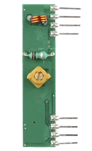
The RF Link Receiver - 4800bps (434MHz), manufactured by WENSHING, is a compact and efficient radio frequency receiver module. It is designed to receive data signals at a baud rate of 4800 bps and operates at a frequency of 434 MHz. This module is widely used in wireless communication systems for transmitting and receiving data over short to medium distances.
Explore Projects Built with RF Link Receiver - 4800bps (434MHz)


Explore Projects Built with RF Link Receiver - 4800bps (434MHz)
Common Applications and Use Cases
- Wireless remote controls (e.g., garage doors, home automation)
- Data transmission in IoT devices
- Wireless sensor networks
- Robotics and remote monitoring systems
- RF-based communication between microcontrollers
Technical Specifications
The following table outlines the key technical details of the RF Link Receiver:
| Parameter | Value |
|---|---|
| Operating Frequency | 434 MHz |
| Baud Rate | 4800 bps |
| Operating Voltage | 5V DC |
| Operating Current | 4.5 mA (typical) |
| Sensitivity | -105 dBm |
| Communication Range | Up to 100 meters (line of sight) |
| Modulation Type | ASK (Amplitude Shift Keying) |
| Dimensions | 30mm x 14mm x 7mm |
Pin Configuration and Descriptions
The RF Link Receiver module has four pins, as described in the table below:
| Pin | Name | Description |
|---|---|---|
| 1 | GND | Ground pin. Connect to the ground of the power supply. |
| 2 | DATA | Data output pin. Outputs the received digital signal. |
| 3 | VCC | Power supply pin. Connect to a 5V DC source. |
| 4 | ANT | Antenna pin. Connect to a 17cm wire or a suitable antenna for better reception. |
Usage Instructions
How to Use the Component in a Circuit
- Power Supply: Connect the
VCCpin to a 5V DC power source and theGNDpin to the ground. - Data Output: Connect the
DATApin to the input pin of a microcontroller or a decoder IC to process the received signal. - Antenna: Attach a 17cm wire or a pre-designed antenna to the
ANTpin to improve signal reception. - Pairing with a Transmitter: Ensure that the RF Link Receiver is paired with a compatible 434 MHz RF transmitter module for proper communication.
Important Considerations and Best Practices
- Antenna Placement: For optimal performance, place the antenna in an open area, away from metal objects or other sources of interference.
- Power Supply Stability: Use a stable 5V power supply to avoid noise or signal distortion.
- Decoding the Signal: The output from the
DATApin is raw digital data. Use a microcontroller or a decoder IC to interpret the signal. - Range Limitations: The communication range is up to 100 meters in line-of-sight conditions. Obstacles like walls or interference may reduce the range.
Example: Connecting to an Arduino UNO
Below is an example of how to connect the RF Link Receiver to an Arduino UNO and read the received data:
Circuit Connections
- Connect the
VCCpin of the receiver to the 5V pin on the Arduino. - Connect the
GNDpin of the receiver to the GND pin on the Arduino. - Connect the
DATApin of the receiver to digital pin 2 on the Arduino. - Attach a 17cm wire to the
ANTpin for the antenna.
Arduino Code
// Example code to read data from the RF Link Receiver (434MHz)
// Connect the DATA pin of the receiver to digital pin 2 on the Arduino.

#define RECEIVER_PIN 2  // Pin connected to the DATA pin of the receiver

void setup() {
  Serial.begin(9600);  // Initialize serial communication at 9600 bps
  pinMode(RECEIVER_PIN, INPUT);  // Set the receiver pin as input
  Serial.println("RF Receiver Ready");
}

void loop() {
  int receivedData = digitalRead(RECEIVER_PIN);  // Read the data from the receiver
  Serial.print("Received Data: ");
  Serial.println(receivedData);  // Print the received data to the Serial Monitor
  delay(100);  // Small delay to avoid flooding the Serial Monitor
}
Troubleshooting and FAQs
Common Issues and Solutions
No Data Received:
- Ensure the transmitter and receiver are operating at the same frequency (434 MHz).
- Check the antenna connection and placement for proper signal reception.
- Verify that the
DATApin is correctly connected to the microcontroller.
Short Communication Range:
- Use a longer or properly tuned antenna for better reception.
- Minimize obstacles and interference between the transmitter and receiver.
Unstable or Noisy Output:
- Use a decoupling capacitor (e.g., 0.1µF) across the power supply pins to reduce noise.
- Ensure a stable 5V power supply is used.
Interference from Other Devices:
- Avoid using the module near devices operating at the same frequency (e.g., other 434 MHz devices).
- Use proper shielding or filters to minimize interference.
FAQs
Q1: Can I use this module with a 3.3V microcontroller?
A1: The module requires a 5V power supply. However, the DATA pin output can often be read by 3.3V logic microcontrollers. Use a level shifter if needed.
Q2: What type of antenna should I use?
A2: A simple 17cm wire works well as an antenna. For better performance, you can use a pre-designed 434 MHz antenna.
Q3: Can this module be used for bi-directional communication?
A3: No, this module is a receiver only. For bi-directional communication, pair it with a compatible RF transmitter module.
Q4: What is the maximum baud rate supported?
A4: The module supports a maximum baud rate of 4800 bps. Ensure the transmitter is configured to the same baud rate.