Cirkit Designer Logo
Cirkit Designer
Your all-in-one circuit design IDE
Home / 
Component Documentation

How to Use trackball: Examples, Pinouts, and Specs

Image of trackball
Cirkit Designer LogoDesign with trackball in Cirkit Designer

Introduction

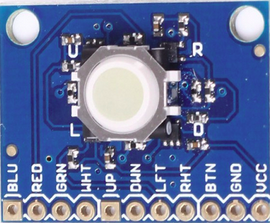
The Adafruit Trackball (Part ID: 5437314a_y315_240702) is an input device designed for precise cursor control. It consists of a ball housed in a socket, which detects rotation in multiple directions. Unlike a traditional mouse, the trackball remains stationary, and the user manipulates the ball directly with their fingers or palm. This makes it an excellent choice for applications requiring fine control or where space constraints limit the use of a standard mouse.

Explore Projects Built with trackball

Use Cirkit Designer to design, explore, and prototype these projects online. Some projects support real-time simulation. Click "Open Project" to start designing instantly!
Arduino Leonardo-Based Gaming Steering Wheel with Pedals and Gear Shifter
Image of DIY Steering Wheel: A project utilizing trackball in a practical application
This circuit is a gaming steering wheel system with 3 pedals and a gear shifter, interfaced with an Arduino Leonardo. It includes a 600 PPR optical rotary encoder for steering, three potentiometers for pedal input, and multiple push buttons connected via an IO expander for gear shifting and additional controls. The Arduino processes inputs from these components and communicates the data for further processing or display.
Cirkit Designer LogoOpen Project in Cirkit Designer
Arduino Nano-Based Wireless Joystick and Motion Controller
Image of hand gesture: A project utilizing trackball in a practical application
This circuit features an Arduino Nano microcontroller interfaced with an HC-05 Bluetooth module, an MPU-6050 accelerometer/gyroscope, and a KY-023 Dual Axis Joystick Module. The Arduino Nano is powered by a 9V battery through a rocker switch and communicates with the HC-05 for Bluetooth connectivity, reads joystick positions from the KY-023 module via analog inputs, and communicates with the MPU-6050 over I2C to capture motion data. The circuit is likely designed for wireless control and motion sensing applications, such as a remote-controlled robot or a game controller.
Cirkit Designer LogoOpen Project in Cirkit Designer
Arduino UNO-Based IR Ball Counter with LCD Display and Servo Control
Image of ball counter: A project utilizing trackball in a practical application
This circuit is an IR ball counter system using an Arduino UNO, two IR sensors, a servo motor, a pushbutton, and a 16x2 I2C LCD. The IR sensors detect the entry and exit of balls, updating the count displayed on the LCD, while the pushbutton resets the count, and the servo motor can be controlled via the Arduino.
Cirkit Designer LogoOpen Project in Cirkit Designer
Arduino Nano-Based Wireless Input Controller with Joysticks and Sensors
Image of TRANSMITTER: A project utilizing trackball in a practical application
This is a multifunctional interactive device featuring dual-axis control via PS2 joysticks, visual feedback through an OLED display, and wireless communication using an NRF24L01 module. It includes a piezo buzzer for sound, tactile buttons for additional user input, rotary potentiometers for analog control, and an MPU-6050 for motion sensing. The Arduino Nano serves as the central processing unit, coordinating input and output functions, with capacitors for power stability.
Cirkit Designer LogoOpen Project in Cirkit Designer

Explore Projects Built with trackball

Use Cirkit Designer to design, explore, and prototype these projects online. Some projects support real-time simulation. Click "Open Project" to start designing instantly!
Image of DIY Steering Wheel: A project utilizing trackball in a practical application
Arduino Leonardo-Based Gaming Steering Wheel with Pedals and Gear Shifter
This circuit is a gaming steering wheel system with 3 pedals and a gear shifter, interfaced with an Arduino Leonardo. It includes a 600 PPR optical rotary encoder for steering, three potentiometers for pedal input, and multiple push buttons connected via an IO expander for gear shifting and additional controls. The Arduino processes inputs from these components and communicates the data for further processing or display.
Cirkit Designer LogoOpen Project in Cirkit Designer
Image of hand gesture: A project utilizing trackball in a practical application
Arduino Nano-Based Wireless Joystick and Motion Controller
This circuit features an Arduino Nano microcontroller interfaced with an HC-05 Bluetooth module, an MPU-6050 accelerometer/gyroscope, and a KY-023 Dual Axis Joystick Module. The Arduino Nano is powered by a 9V battery through a rocker switch and communicates with the HC-05 for Bluetooth connectivity, reads joystick positions from the KY-023 module via analog inputs, and communicates with the MPU-6050 over I2C to capture motion data. The circuit is likely designed for wireless control and motion sensing applications, such as a remote-controlled robot or a game controller.
Cirkit Designer LogoOpen Project in Cirkit Designer
Image of ball counter: A project utilizing trackball in a practical application
Arduino UNO-Based IR Ball Counter with LCD Display and Servo Control
This circuit is an IR ball counter system using an Arduino UNO, two IR sensors, a servo motor, a pushbutton, and a 16x2 I2C LCD. The IR sensors detect the entry and exit of balls, updating the count displayed on the LCD, while the pushbutton resets the count, and the servo motor can be controlled via the Arduino.
Cirkit Designer LogoOpen Project in Cirkit Designer
Image of TRANSMITTER: A project utilizing trackball in a practical application
Arduino Nano-Based Wireless Input Controller with Joysticks and Sensors
This is a multifunctional interactive device featuring dual-axis control via PS2 joysticks, visual feedback through an OLED display, and wireless communication using an NRF24L01 module. It includes a piezo buzzer for sound, tactile buttons for additional user input, rotary potentiometers for analog control, and an MPU-6050 for motion sensing. The Arduino Nano serves as the central processing unit, coordinating input and output functions, with capacitors for power stability.
Cirkit Designer LogoOpen Project in Cirkit Designer

Common Applications and Use Cases

  • Computer Input Devices: Used as an alternative to a mouse for precise cursor control.
  • Embedded Systems: Ideal for projects requiring compact and versatile input solutions.
  • Gaming: Provides smooth and accurate control for gaming applications.
  • Assistive Technology: Useful for individuals with limited mobility or dexterity.
  • Industrial Controls: Employed in machinery or equipment requiring precise input in constrained spaces.

Technical Specifications

Key Technical Details

  • Manufacturer: Adafruit
  • Part ID: 5437314a_y315_240702
  • Input Type: Mechanical ball rotation detection
  • Interface: I2C communication protocol
  • Operating Voltage: 3.3V to 5V
  • Current Consumption: ~10mA (typical)
  • Dimensions: 35mm x 35mm x 20mm
  • Ball Diameter: 14mm
  • Built-in Features: RGB LED for visual feedback, configurable via I2C
  • Operating Temperature: -20°C to 70°C

Pin Configuration and Descriptions

The Adafruit Trackball has a 6-pin header for interfacing with microcontrollers. Below is the pinout:

Pin Name Description
1 VIN Power input (3.3V to 5V). Supplies power to the trackball.
2 GND Ground connection.
3 SCL I2C clock line. Used for communication with the microcontroller.
4 SDA I2C data line. Used for communication with the microcontroller.
5 INT Interrupt pin. Signals when new data is available (optional use).
6 RST Reset pin. Resets the trackball module when pulled low (optional use).

Usage Instructions

How to Use the Component in a Circuit

  1. Power the Trackball: Connect the VIN pin to a 3.3V or 5V power source and the GND pin to ground.
  2. I2C Communication: Connect the SCL and SDA pins to the corresponding I2C pins on your microcontroller (e.g., Arduino UNO: A5 for SCL, A4 for SDA).
  3. Optional Connections:
    • Use the INT pin to detect when new data is available.
    • Connect the RST pin to a GPIO pin if you need to reset the module programmatically.
  4. Install Required Libraries: For Arduino, install the Adafruit Trackball library via the Arduino Library Manager.
  5. Write Code: Use the library functions to initialize the trackball, read movement data, and control the RGB LED.

Important Considerations and Best Practices

  • Pull-up Resistors: Ensure that the I2C lines (SCL and SDA) have pull-up resistors (typically 4.7kΩ). Many microcontrollers, including Arduino boards, have built-in pull-ups.
  • Debouncing: If using the INT pin, implement software debouncing to avoid false triggers.
  • Power Supply: Use a stable power source to avoid erratic behavior.
  • Ball Maintenance: Keep the ball and socket clean to ensure smooth operation and accurate readings.

Example Arduino Code

Below is an example of how to use the Adafruit Trackball with an Arduino UNO:

#include <Wire.h>
#include <Adafruit_Trackball.h>

// Create an instance of the Adafruit Trackball library
Adafruit_Trackball trackball;

void setup() {
  Serial.begin(9600); // Initialize serial communication for debugging
  Wire.begin();       // Initialize I2C communication

  // Initialize the trackball
  if (!trackball.begin()) {
    Serial.println("Trackball not detected. Check connections!");
    while (1); // Halt execution if initialization fails
  }
  Serial.println("Trackball initialized successfully!");

  // Set the RGB LED to a default color (e.g., blue)
  trackball.setLED(0, 0, 255); // RGB values: Red=0, Green=0, Blue=255
}

void loop() {
  // Check for movement data
  if (trackball.available()) {
    int8_t x, y;
    trackball.read(&x, &y); // Read X and Y movement data

    // Print movement data to the serial monitor
    Serial.print("X: ");
    Serial.print(x);
    Serial.print(" Y: ");
    Serial.println(y);
  }

  delay(10); // Small delay to avoid overwhelming the serial monitor
}

Troubleshooting and FAQs

Common Issues and Solutions

  1. Trackball Not Detected:

    • Cause: Incorrect wiring or I2C address mismatch.
    • Solution: Double-check the connections and ensure the I2C address matches the library's default (0x0A).
  2. No Movement Data:

    • Cause: Ball not seated properly or dirty socket.
    • Solution: Clean the ball and socket with a soft cloth and ensure the ball rotates freely.
  3. RGB LED Not Working:

    • Cause: Incorrect library usage or insufficient power.
    • Solution: Verify the setLED() function is called with valid RGB values and ensure the power supply is stable.
  4. Intermittent I2C Communication:

    • Cause: Missing or incorrect pull-up resistors on the I2C lines.
    • Solution: Add 4.7kΩ pull-up resistors to the SCL and SDA lines if not already present.

FAQs

  • Q: Can the trackball be used with 3.3V microcontrollers like the Raspberry Pi?

    • A: Yes, the trackball is compatible with both 3.3V and 5V logic levels.
  • Q: How do I change the I2C address of the trackball?

    • A: The I2C address is fixed at 0x0A and cannot be changed.
  • Q: Can I use multiple trackballs on the same I2C bus?

    • A: No, since the I2C address is fixed, only one trackball can be used per I2C bus.
  • Q: How do I reset the trackball?

    • A: Pull the RST pin low momentarily to reset the module.

This documentation provides a comprehensive guide to using the Adafruit Trackball (Part ID: 5437314a_y315_240702). For further assistance, refer to the Adafruit support forums or the official product page.