
How to Use Netduino Plus2: Examples, Pinouts, and Specs
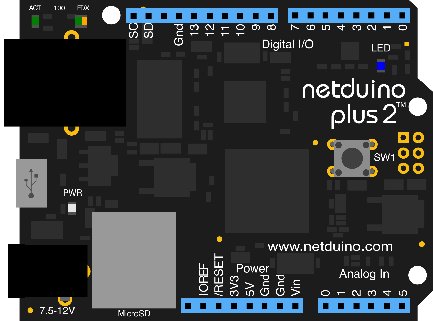
 Design with Netduino Plus2 in Cirkit Designer
Introduction
The Netduino Plus2 is an open-source hardware platform designed for developers and hobbyists to create Internet of Things (IoT) applications. Manufactured by Netduino, this microcontroller board features an ARM Cortex-M4 processor, digital and analog I/O pins, and built-in Ethernet connectivity. Its compatibility with the .NET Micro Framework makes it an excellent choice for developers familiar with C# and Visual Studio.
Explore Projects Built with Netduino Plus2
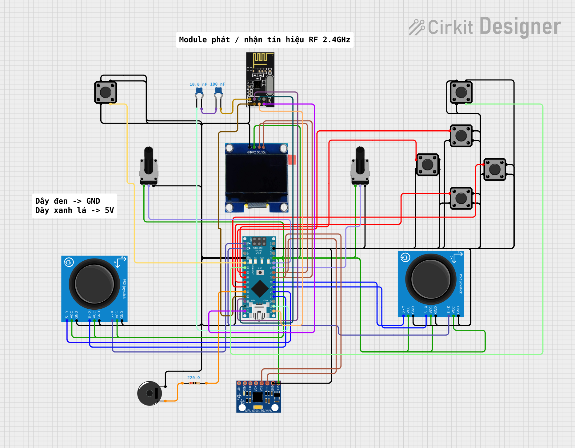 Open Project in Cirkit Designer
 Open Project in Cirkit Designer
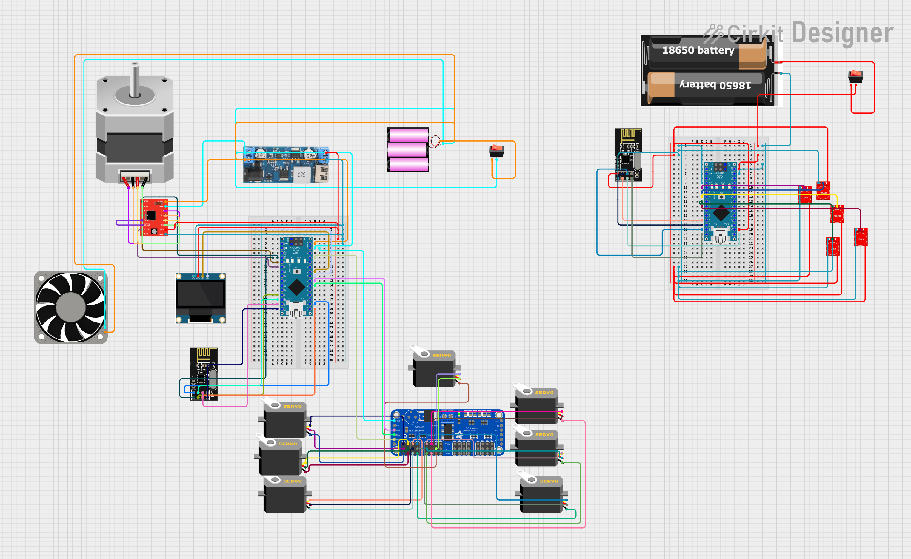 Open Project in Cirkit Designer
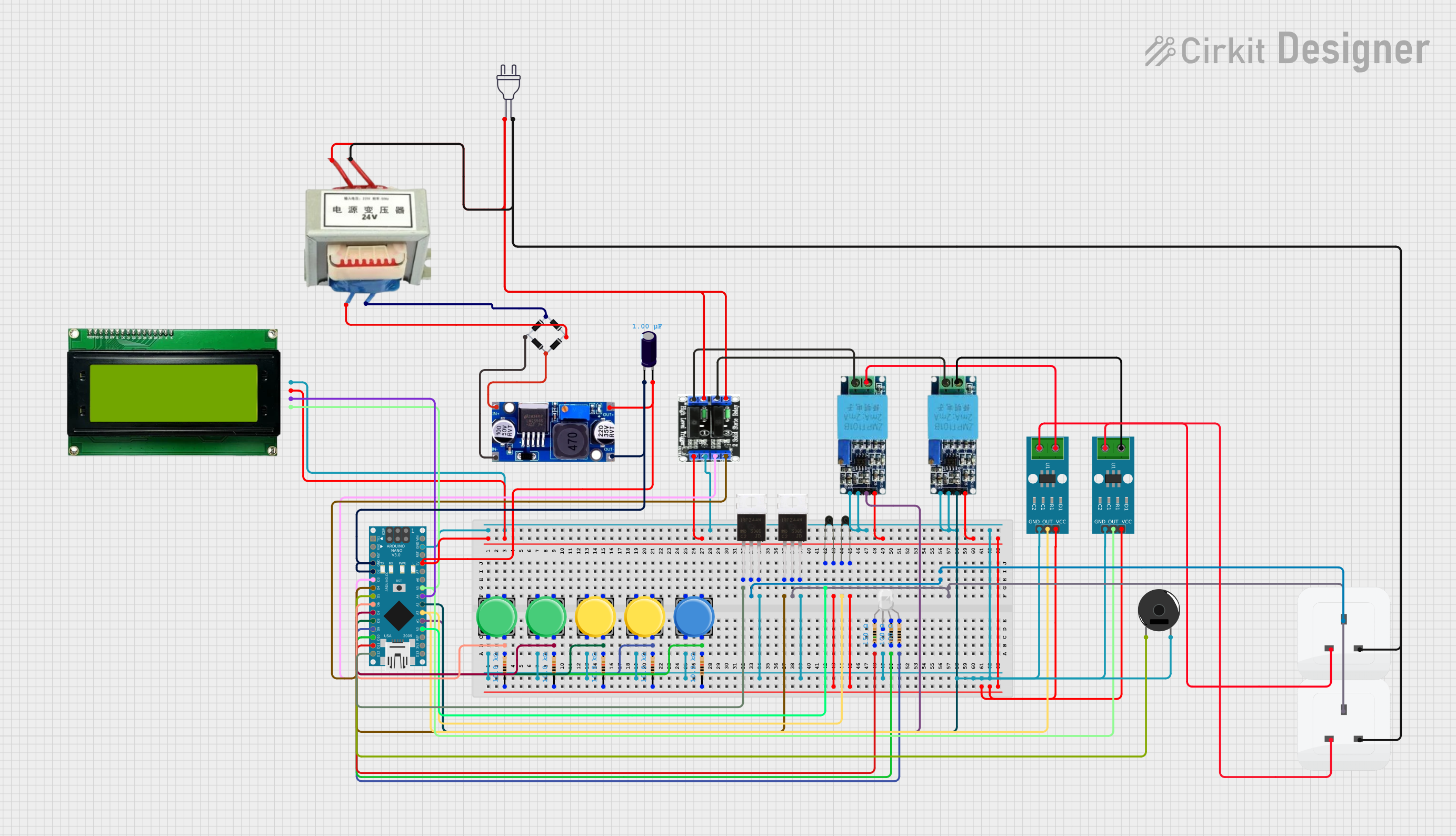 Open Project in Cirkit Designer
Explore Projects Built with Netduino Plus2
Open Project in Cirkit DesignerOpen Project in Cirkit DesignerOpen Project in Cirkit DesignerOpen Project in Cirkit DesignerCommon Applications and Use Cases
- IoT devices and smart home automation
- Prototyping networked embedded systems
- Data logging and remote monitoring
- Educational projects for learning embedded systems and networking
- Integration with cloud services for IoT applications
Technical Specifications
The Netduino Plus2 is equipped with robust hardware and networking capabilities, making it suitable for a wide range of applications. Below are its key technical details:
Key Technical Details
| Specification | Value |
|---|---|
| Processor | ARM Cortex-M4 (STM32F405RG) |
| Clock Speed | 168 MHz |
| Flash Memory | 384 KB |
| RAM | 100 KB |
| Digital I/O Pins | 22 (including 6 PWM-capable pins) |
| Analog Input Pins | 6 |
| Communication Interfaces | UART, SPI, I2C |
| Ethernet | 10/100 Mbps Ethernet |
| Input Voltage (via VIN) | 7-12V |
| USB Power Supply | 5V |
| Operating Voltage | 3.3V |
| Dimensions | 2.7 x 2.1 inches (68.6 x 53.3 mm) |
Pin Configuration and Descriptions
The Netduino Plus2 features a variety of pins for digital, analog, and communication purposes. Below is a detailed pinout description:
Digital I/O Pins
| Pin Number | Function | Description |
|---|---|---|
| D0-D13 | Digital I/O | General-purpose digital pins |
| D3, D5, D6, D9, D10, D11 | PWM Output | Pulse-width modulation capable pins |
Analog Input Pins
| Pin Number | Function | Description |
|---|---|---|
| A0-A5 | Analog Input | 12-bit ADC for reading analog signals |
Communication Pins
| Pin Number | Function | Description |
|---|---|---|
| TX (D1) | UART Transmit | Serial communication transmit pin |
| RX (D0) | UART Receive | Serial communication receive pin |
| SCL, SDA | I2C Communication | Clock and data lines for I2C |
| SCK, MISO, MOSI | SPI Communication | SPI clock, input, and output pins |
Power Pins
| Pin Number | Function | Description |
|---|---|---|
| VIN | Input Voltage | External power supply (7-12V) |
| 3.3V | Regulated Output Voltage | 3.3V output for external components |
| GND | Ground | Common ground for the circuit |
Usage Instructions
The Netduino Plus2 is designed to be user-friendly and versatile. Follow these steps to get started:
Setting Up the Netduino Plus2
- Install the .NET Micro Framework SDK: Download and install the .NET Micro Framework SDK and the Netduino SDK from the official Netduino website.
- Connect the Board: Use a micro-USB cable to connect the Netduino Plus2 to your computer. Ensure the drivers are installed correctly.
- Set Up the Development Environment: Open Visual Studio and create a new .NET Micro Framework project. Select the appropriate target framework for the Netduino Plus2.
- Power the Board: The board can be powered via USB or an external power supply (7-12V via the VIN pin).
Writing and Deploying Code
Below is an example of a simple program to blink an LED connected to pin D13:
using System;
using System.Threading;
using Microsoft.SPOT.Hardware;
using SecretLabs.NETMF.Hardware.Netduino;

namespace NetduinoPlus2Example
{
    public class Program
    {
        public static void Main()
        {
            // Initialize the LED pin (D13) as an output
            OutputPort led = new OutputPort(Pins.ONBOARD_LED, false);

            while (true)
            {
                led.Write(true);  // Turn the LED on
                Thread.Sleep(500); // Wait for 500 milliseconds

                led.Write(false); // Turn the LED off
                Thread.Sleep(500); // Wait for 500 milliseconds
            }
        }
    }
}
Important Considerations and Best Practices
- Power Supply: Ensure the board is powered within the recommended voltage range (7-12V via VIN or 5V via USB).
- Ethernet Usage: When using Ethernet, ensure the network cable is securely connected, and the network settings are configured correctly in your code.
- Pin Voltage Levels: The I/O pins operate at 3.3V. Avoid applying higher voltages to prevent damage.
- Debugging: Use Visual Studio's debugging tools to step through your code and identify issues.
Troubleshooting and FAQs
Common Issues and Solutions
The board is not detected by the computer:
- Ensure the USB cable is properly connected and functional.
- Verify that the correct drivers are installed.
- Try using a different USB port or cable.
Code deployment fails:
- Check that the correct target framework is selected in Visual Studio.
- Ensure the board is powered and connected to the computer.
- Restart the board and try deploying the code again.
Ethernet connection issues:
- Verify the Ethernet cable is securely connected.
- Check the network configuration in your code (e.g., IP address, subnet mask).
- Test the network connection with another device to rule out hardware issues.
FAQs
Q: Can I use the Netduino Plus2 with Arduino shields?
A: Yes, the Netduino Plus2 is compatible with most Arduino shields, but ensure the shield operates at 3.3V logic levels.
Q: What programming languages are supported?
A: The Netduino Plus2 supports C# and the .NET Micro Framework.
Q: How do I reset the board?
A: Press the reset button on the board to restart it. This does not erase the deployed code.
Q: Can I use the board without Visual Studio?
A: While Visual Studio is the recommended IDE, you can use other tools that support the .NET Micro Framework, but setup may be more complex.
By following this documentation, you can effectively utilize the Netduino Plus2 for your IoT and embedded system projects.