How to Use plug jack stereo: Examples, Pinouts, and Specs
Introduction
A plug jack stereo is an audio connector designed for transmitting stereo audio signals, typically featuring two channels: left and right. It is widely used in audio equipment such as headphones, speakers, amplifiers, and other devices to facilitate high-quality sound transmission. The plug jack stereo is available in various sizes, including 2.5mm, 3.5mm, and 6.35mm, with the 3.5mm variant being the most common for consumer electronics.
Explore Projects Built with plug jack stereo

Explore Projects Built with plug jack stereo
Common Applications and Use Cases
- Connecting headphones or earphones to audio devices
- Linking audio output from computers, smartphones, or tablets to speakers
- Interfacing with audio amplifiers and mixers
- Used in musical instruments such as electric guitars and keyboards
- Audio recording and playback systems
Technical Specifications
Below are the general technical specifications for a standard 3.5mm plug jack stereo:
| Parameter | Specification |
|---|---|
| Connector Type | Stereo audio jack |
| Number of Channels | 2 (Left and Right) |
| Typical Impedance | 32Ω to 600Ω (depending on application) |
| Voltage Rating | 12V DC (typical for audio signals) |
| Current Rating | 1A (maximum) |
| Contact Material | Gold-plated or nickel-plated brass |
| Insulation Material | Plastic or thermoplastic |
| Operating Temperature | -20°C to 70°C |
Pin Configuration and Descriptions
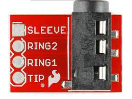
The plug jack stereo typically has three main contacts: Tip, Ring, and Sleeve (TRS). Below is the pin configuration:
| Pin | Name | Description |
|---|---|---|
| Tip | Left | Carries the left audio channel signal |
| Ring | Right | Carries the right audio channel signal |
| Sleeve | Ground | Serves as the common ground for both audio channels |
For a 4-pole stereo jack (TRRS), an additional pin is included for microphone or video signals.
| Pin | Name | Description |
|---|---|---|
| Tip | Left | Carries the left audio channel signal |
| Ring 1 | Right | Carries the right audio channel signal |
| Ring 2 | Mic/Video | Carries microphone or video signal (optional) |
| Sleeve | Ground | Serves as the common ground for all signals |
Usage Instructions
How to Use the Plug Jack Stereo in a Circuit
- Identify the Pins: Determine the Tip, Ring, and Sleeve (TRS) connections on the plug jack stereo. For TRRS jacks, identify the additional Ring 2 pin.
- Connect to Audio Source: Solder or connect the Tip to the left audio channel, the Ring to the right audio channel, and the Sleeve to the ground.
- Ensure Proper Insulation: Use heat shrink tubing or other insulation materials to prevent short circuits between the pins.
- Test the Connection: Use a multimeter to verify continuity and ensure proper connections before powering the circuit.
Important Considerations and Best Practices
- Avoid Overloading: Ensure the audio signal voltage and current do not exceed the component's ratings.
- Use Shielded Cables: To minimize noise and interference, use shielded audio cables for connections.
- Match Impedance: Ensure the impedance of the connected devices is compatible to avoid signal loss or distortion.
- Handle with Care: Avoid excessive force when inserting or removing the plug to prevent damage to the jack or connected devices.
Example: Connecting a Plug Jack Stereo to an Arduino UNO
The plug jack stereo can be used with an Arduino UNO to process audio signals. Below is an example of reading an audio signal from the left channel using the analog input pin.
// Example: Reading audio signal from a stereo jack's left channel
// Connect the Tip (Left channel) to A0, Sleeve (Ground) to GND

const int audioPin = A0; // Analog pin connected to the left channel
int audioValue = 0;      // Variable to store the audio signal value

void setup() {
  Serial.begin(9600); // Initialize serial communication
}

void loop() {
  audioValue = analogRead(audioPin); // Read the audio signal
  Serial.println(audioValue);       // Print the signal value to the Serial Monitor
  delay(10);                        // Small delay for stability
}
Note: The Arduino UNO can only read DC signals. To process AC audio signals, use a coupling capacitor to block the DC offset.
Troubleshooting and FAQs
Common Issues and Solutions
No Audio Output
- Cause: Incorrect wiring or loose connections.
- Solution: Verify the connections for the Tip, Ring, and Sleeve. Ensure proper soldering or secure connections.
Distorted Audio
- Cause: Impedance mismatch or interference.
- Solution: Use devices with matching impedance and shielded cables to reduce noise.
Intermittent Signal
- Cause: Worn-out or dirty contacts.
- Solution: Clean the plug and jack contacts with isopropyl alcohol and ensure a snug fit.
Arduino Not Reading Signal
- Cause: AC signal not properly coupled to the Arduino.
- Solution: Add a coupling capacitor (e.g., 10µF) between the audio source and the Arduino input pin.
FAQs
Q: Can I use a 3.5mm plug jack stereo for mono audio?
A: Yes, you can use a stereo jack for mono audio by connecting both the Tip and Ring to the same audio signal.
Q: What is the difference between TRS and TRRS connectors?
A: TRS connectors have three contacts (Tip, Ring, Sleeve) for stereo audio, while TRRS connectors have four contacts (Tip, Ring 1, Ring 2, Sleeve) to support additional signals like a microphone or video.
Q: How do I prevent noise in my audio signal?
A: Use shielded cables, ensure proper grounding, and avoid running audio cables near power lines or other sources of interference.
Q: Can I use a plug jack stereo for digital audio signals?
A: While plug jack stereos are primarily designed for analog audio, they can transmit digital audio signals if the connected devices support it. However, specialized connectors like optical or HDMI are better suited for digital audio.