Cirkit Designer Logo
Cirkit Designer
Your all-in-one circuit design IDE
Home / 
Component Documentation

How to Use laser module: Examples, Pinouts, and Specs

Image of laser module
Cirkit Designer LogoDesign with laser module in Cirkit Designer

Introduction

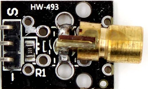
A laser module is a device that emits a coherent beam of light through the process of stimulated emission. It typically consists of a laser diode, optics for beam shaping or focusing, and often a protective housing. Laser modules are widely used in applications such as optical communication, distance measurement, barcode scanning, material processing, and laser pointers. Their ability to produce highly focused and precise beams makes them indispensable in both industrial and consumer applications.

Explore Projects Built with laser module

Use Cirkit Designer to design, explore, and prototype these projects online. Some projects support real-time simulation. Click "Open Project" to start designing instantly!
Arduino Uno R3-Based Security System with Laser Tripwire, GSM Notification, and Motion Detection
Image of SECURITY SYSTEM: A project utilizing laser module in a practical application
This circuit features an Arduino Uno R3 as the central controller, interfaced with a KY-008 Laser Emitter, an LDR module, a buzzer, a Sim800l GSM module, and an MPU-6050 accelerometer/gyroscope. The Arduino controls the laser emitter and buzzer, reads analog values from the LDR, communicates with the Sim800l via serial (RX/TX), and interfaces with the MPU-6050 over I2C (SCL/SDA). The circuit is likely designed for sensing light intensity, motion detection, and communication via GSM, with the capability to emit laser light and sound alerts.
Cirkit Designer LogoOpen Project in Cirkit Designer
Battery-Powered Laser Emitter with Solar Charging and LED Indicator
Image of rx: A project utilizing laser module in a practical application
This circuit is a solar-powered laser emitter system with an LED indicator. The solar panel charges a 18650 battery via a TP4056 charging module, and a push button controls the activation of the laser emitter and the LED through a MOSFET switch.
Cirkit Designer LogoOpen Project in Cirkit Designer
Arduino UNO Laser Tripwire Security System with GSM Alert
Image of Laser home security system: A project utilizing laser module in a practical application
This circuit is a laser tripwire security system using an Arduino UNO. When the laser beam is interrupted, the system triggers a buzzer, lights up an LED, and sends an alert via a SIM800L GSM module. The system also includes an LDR module to detect the laser beam and two LEDs to indicate the system status.
Cirkit Designer LogoOpen Project in Cirkit Designer
Solar-Powered ESP32 Security System with RFID and Laser Detection
Image of CPE doorlock: A project utilizing laser module in a practical application
This circuit appears to be a complex system with multiple sensors and actuators controlled by an ESP32 microcontroller. It includes a laser emitter and receiver for detection purposes, a PIR sensor for motion detection, an RFID reader for identification tasks, and a keypad for user input. The system also features a relay-controlled solenoid lock, visual indicators (LEDs), a buzzer for audio feedback, and an LCD for display, all interfaced through an IO expander. Power management is handled by a solar panel with a charge controller, an AC source with an automatic transfer switch (ATS), and a voltage regulator (buck converter).
Cirkit Designer LogoOpen Project in Cirkit Designer

Explore Projects Built with laser module

Use Cirkit Designer to design, explore, and prototype these projects online. Some projects support real-time simulation. Click "Open Project" to start designing instantly!
Image of SECURITY SYSTEM: A project utilizing laser module in a practical application
Arduino Uno R3-Based Security System with Laser Tripwire, GSM Notification, and Motion Detection
This circuit features an Arduino Uno R3 as the central controller, interfaced with a KY-008 Laser Emitter, an LDR module, a buzzer, a Sim800l GSM module, and an MPU-6050 accelerometer/gyroscope. The Arduino controls the laser emitter and buzzer, reads analog values from the LDR, communicates with the Sim800l via serial (RX/TX), and interfaces with the MPU-6050 over I2C (SCL/SDA). The circuit is likely designed for sensing light intensity, motion detection, and communication via GSM, with the capability to emit laser light and sound alerts.
Cirkit Designer LogoOpen Project in Cirkit Designer
Image of rx: A project utilizing laser module in a practical application
Battery-Powered Laser Emitter with Solar Charging and LED Indicator
This circuit is a solar-powered laser emitter system with an LED indicator. The solar panel charges a 18650 battery via a TP4056 charging module, and a push button controls the activation of the laser emitter and the LED through a MOSFET switch.
Cirkit Designer LogoOpen Project in Cirkit Designer
Image of Laser home security system: A project utilizing laser module in a practical application
Arduino UNO Laser Tripwire Security System with GSM Alert
This circuit is a laser tripwire security system using an Arduino UNO. When the laser beam is interrupted, the system triggers a buzzer, lights up an LED, and sends an alert via a SIM800L GSM module. The system also includes an LDR module to detect the laser beam and two LEDs to indicate the system status.
Cirkit Designer LogoOpen Project in Cirkit Designer
Image of CPE doorlock: A project utilizing laser module in a practical application
Solar-Powered ESP32 Security System with RFID and Laser Detection
This circuit appears to be a complex system with multiple sensors and actuators controlled by an ESP32 microcontroller. It includes a laser emitter and receiver for detection purposes, a PIR sensor for motion detection, an RFID reader for identification tasks, and a keypad for user input. The system also features a relay-controlled solenoid lock, visual indicators (LEDs), a buzzer for audio feedback, and an LCD for display, all interfaced through an IO expander. Power management is handled by a solar panel with a charge controller, an AC source with an automatic transfer switch (ATS), and a voltage regulator (buck converter).
Cirkit Designer LogoOpen Project in Cirkit Designer

Technical Specifications

Below are the general technical specifications for a standard laser module. Note that specific models may vary, so always refer to the datasheet of your particular module.

General Specifications

  • Wavelength: 650 nm (red), 532 nm (green), or other depending on the module
  • Output Power: 1 mW to 100 mW (varies by model)
  • Operating Voltage: 3V to 5V DC
  • Operating Current: 20 mA to 200 mA
  • Beam Divergence: < 1.5 mrad
  • Focus: Adjustable (on some models)
  • Operating Temperature: -10°C to 50°C

Pin Configuration

The laser module typically has three pins or wires for connection. Below is a table describing the pin configuration:

Pin/Wire Description Notes
VCC Positive Power Supply Connect to 3V-5V DC power source
GND Ground Connect to the ground of the circuit
TTL/Control Modulation Input (Optional) Used for enabling/disabling the laser or PWM control

Note: Some laser modules may only have two wires (VCC and GND) without a TTL/Control pin.

Usage Instructions

How to Use the Laser Module in a Circuit

  1. Power Supply: Connect the VCC pin to a 3V-5V DC power source and the GND pin to the ground of your circuit.
  2. Control Signal (if available): If the module has a TTL/Control pin, you can use it to turn the laser on/off or modulate the beam using a PWM signal.
  3. Mounting: Secure the laser module in a stable position to ensure accurate beam alignment.
  4. Focusing: If the module has an adjustable focus, rotate the lens to achieve the desired beam sharpness.

Important Considerations and Best Practices

  • Safety First: Always avoid direct eye exposure to the laser beam. Use appropriate laser safety goggles if necessary.
  • Current Limiting: Ensure the power supply provides the correct voltage and current to avoid damaging the laser diode.
  • Heat Management: For high-power modules, consider adding a heatsink or cooling mechanism to prevent overheating.
  • Modulation: Use the TTL/Control pin for precise control of the laser beam, such as turning it on/off or dimming it via PWM.

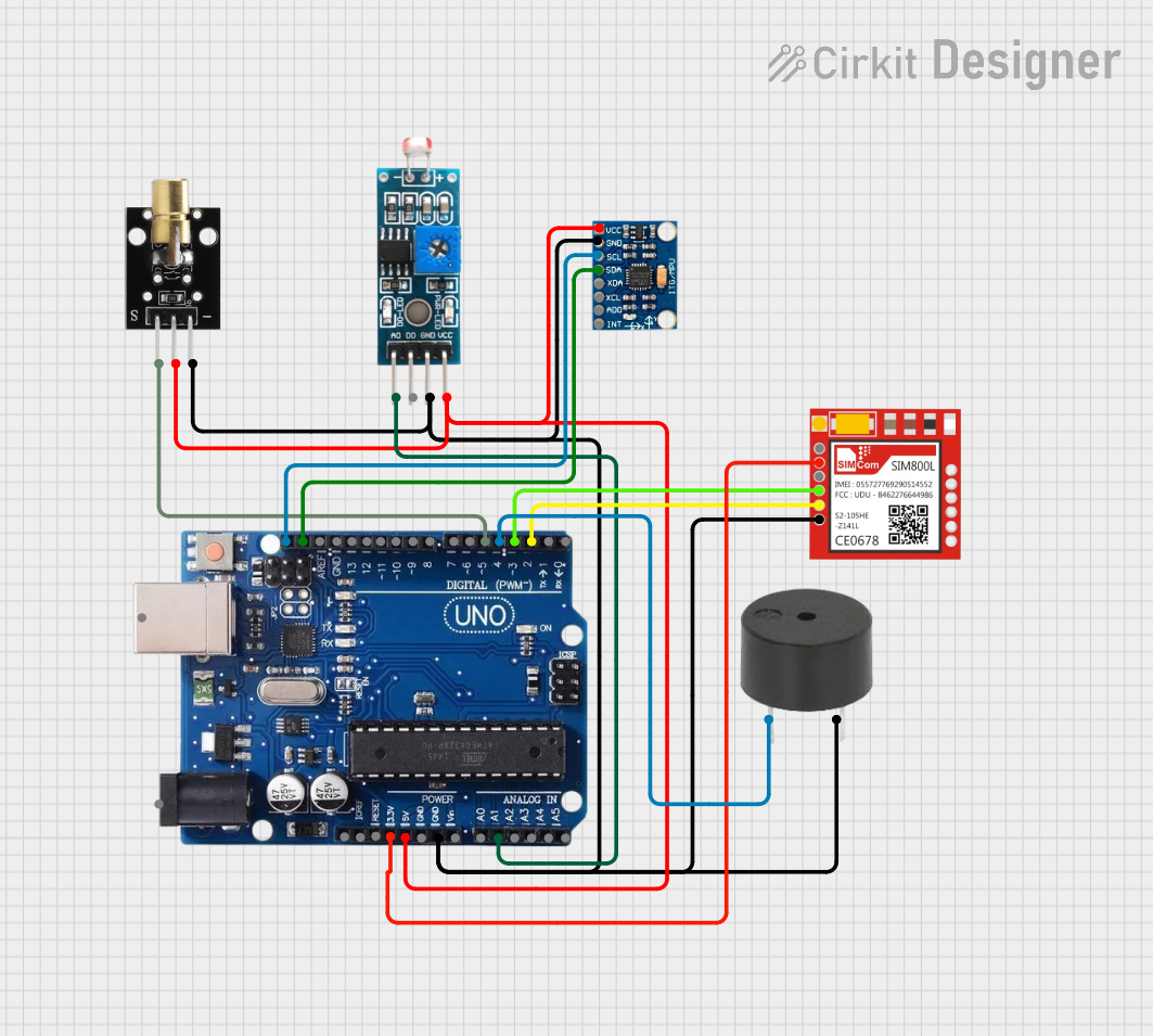
Example: Connecting a Laser Module to an Arduino UNO

Below is an example of how to connect and control a laser module using an Arduino UNO:

Circuit Diagram

  • Connect the VCC pin of the laser module to the 5V pin on the Arduino.
  • Connect the GND pin of the laser module to the GND pin on the Arduino.
  • If the module has a TTL/Control pin, connect it to a digital pin on the Arduino (e.g., pin 9).

Arduino Code

// Laser Module Control with Arduino UNO
// This code turns the laser module on and off at 1-second intervals.

const int laserPin = 9; // Pin connected to the TTL/Control pin of the laser module

void setup() {
  pinMode(laserPin, OUTPUT); // Set the laser pin as an output
}

void loop() {
  digitalWrite(laserPin, HIGH); // Turn the laser on
  delay(1000);                  // Wait for 1 second
  digitalWrite(laserPin, LOW);  // Turn the laser off
  delay(1000);                  // Wait for 1 second
}

Note: If your laser module does not have a TTL/Control pin, it will turn on as soon as power is applied to the VCC and GND pins.

Troubleshooting and FAQs

Common Issues and Solutions

  1. Laser Does Not Turn On

    • Cause: Insufficient power supply or incorrect wiring.
    • Solution: Verify that the power supply provides the correct voltage and current. Double-check the wiring connections.
  2. Beam is Dim or Unstable

    • Cause: Low input voltage or overheating.
    • Solution: Ensure the power supply is stable and within the specified range. Add a heatsink if necessary.
  3. Laser Module Overheats

    • Cause: Prolonged use or insufficient cooling.
    • Solution: Limit the operating time or add a cooling mechanism such as a heatsink or fan.
  4. No Response to TTL/Control Signal

    • Cause: Incorrect signal level or damaged control pin.
    • Solution: Verify that the control signal is within the specified voltage range (typically 0V for LOW and 5V for HIGH).

FAQs

  • Q: Can I power the laser module directly from a 9V battery?
    A: No, most laser modules are designed for 3V-5V operation. Using a 9V battery without a voltage regulator may damage the module.

  • Q: Is it safe to use the laser module without protective goggles?
    A: No, even low-power lasers can cause eye damage. Always use appropriate laser safety goggles.

  • Q: Can I use the laser module outdoors?
    A: Yes, but ensure the module is protected from moisture and extreme temperatures.

  • Q: How do I adjust the focus of the laser beam?
    A: Rotate the lens on the front of the module (if adjustable) to achieve the desired focus.

By following this documentation, you can safely and effectively use a laser module in your projects. Always prioritize safety and consult the module's datasheet for specific details.