How to Use Foxeer M10Q-180 GPS: Examples, Pinouts, and Specs
Introduction
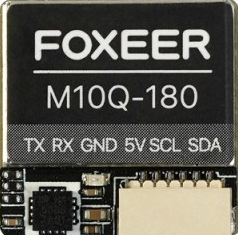
The Foxeer M10Q-180 GPS is a compact and high-performance GPS module designed for drones, RC vehicles, and other applications requiring precise positioning data. With its high refresh rate, low power consumption, and robust design, this GPS module is ideal for use in environments where accuracy and reliability are critical. Its small form factor makes it easy to integrate into a variety of systems, while its advanced features ensure consistent performance.
Explore Projects Built with Foxeer M10Q-180 GPS


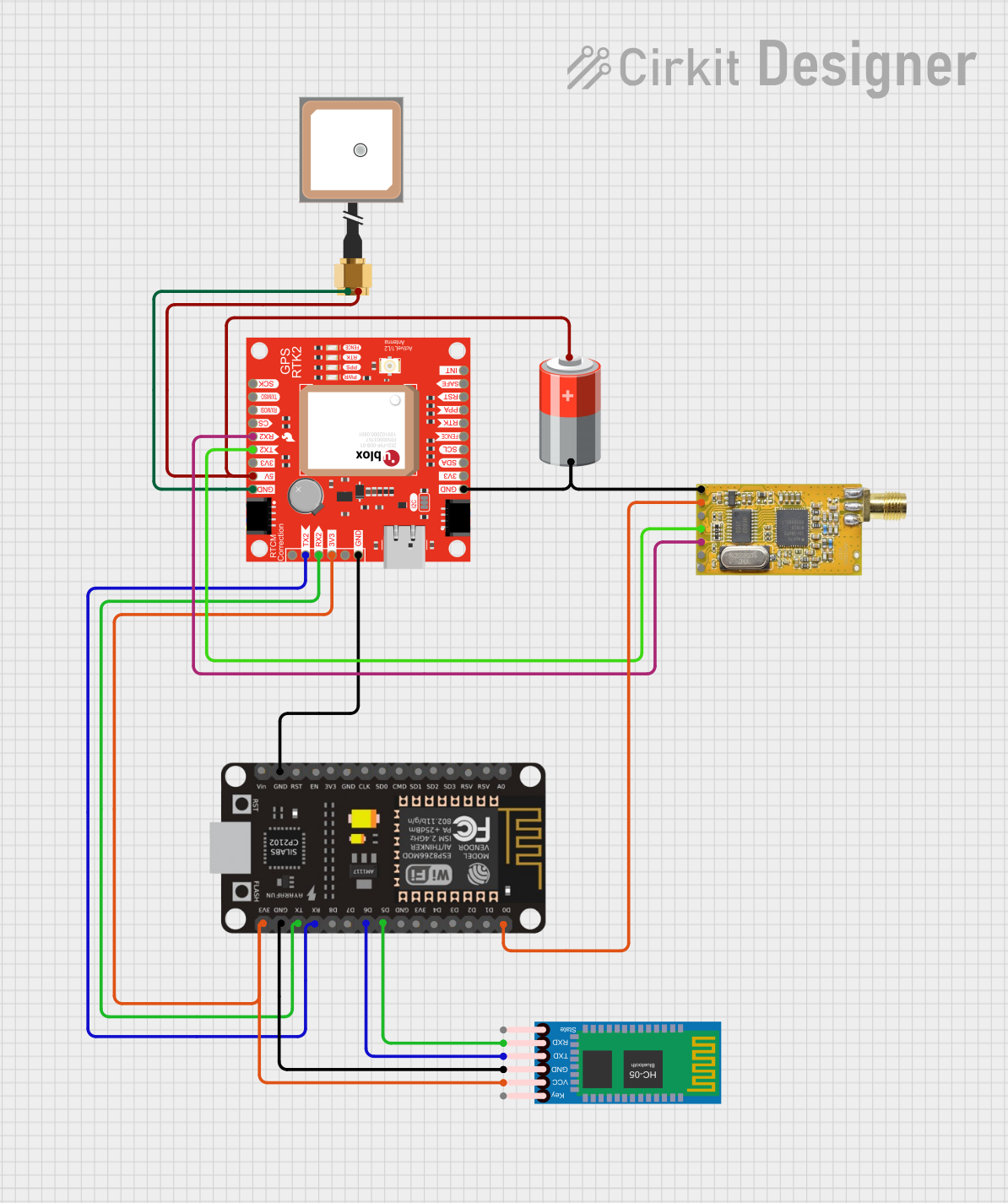
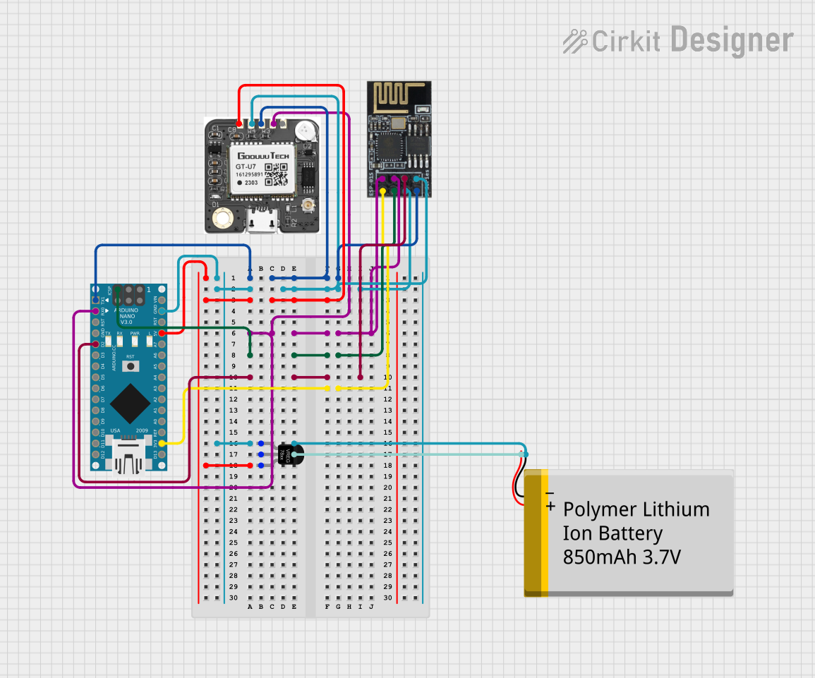
Explore Projects Built with Foxeer M10Q-180 GPS
Common Applications and Use Cases
- GPS navigation for drones and RC vehicles
- Autonomous vehicle positioning
- Geographic data logging
- Real-time tracking systems
- Robotics requiring precise location data
Technical Specifications
The Foxeer M10Q-180 GPS module is built to deliver reliable performance in a compact package. Below are its key technical details:
| Parameter | Specification |
|---|---|
| Chipset | u-blox M10 |
| Positioning System | GPS, GLONASS, Galileo, BeiDou |
| Refresh Rate | Up to 10 Hz |
| Input Voltage | 3.3V - 5.0V |
| Power Consumption | < 30 mA |
| Communication | UART (default baud rate: 9600 bps) |
| Antenna | Built-in ceramic patch antenna |
| Dimensions | 18 mm x 18 mm x 6 mm |
| Weight | 5 grams |
| Operating Temperature | -40°C to +85°C |
Pin Configuration and Descriptions
The Foxeer M10Q-180 GPS module has a simple pinout for easy integration. Below is the pin configuration:
| Pin | Name | Description |
|---|---|---|
| 1 | VCC | Power input (3.3V - 5.0V) |
| 2 | GND | Ground |
| 3 | TX | UART Transmit (GPS data output) |
| 4 | RX | UART Receive (for configuration input) |
Usage Instructions
How to Use the Component in a Circuit
- Power Supply: Connect the
VCCpin to a 3.3V or 5.0V power source and theGNDpin to the ground of your circuit. - Data Communication: Use the
TXpin to receive GPS data from the module. If configuration is required, connect theRXpin to send commands to the module. - Antenna Placement: Ensure the built-in ceramic patch antenna has a clear view of the sky for optimal satellite reception.
- Microcontroller Connection: Connect the
TXpin of the GPS module to the RX pin of your microcontroller (e.g., Arduino UNO) and theRXpin of the GPS module to the TX pin of the microcontroller.
Important Considerations and Best Practices
- Power Stability: Use a stable power source to avoid fluctuations that may affect GPS performance.
- Antenna Orientation: Place the module with the antenna facing upward and away from obstructions or sources of interference.
- Baud Rate: Ensure the baud rate of your microcontroller matches the GPS module's default baud rate (9600 bps) or configure it as needed.
- Cold Start vs. Warm Start: The module may take longer to acquire a GPS fix during a cold start (first power-up) compared to a warm start (subsequent power-ups).
Example Code for Arduino UNO
Below is an example of how to interface the Foxeer M10Q-180 GPS module with an Arduino UNO to read GPS data:
#include <SoftwareSerial.h>

// Define RX and TX pins for the GPS module
SoftwareSerial gpsSerial(4, 3); // RX = Pin 4, TX = Pin 3

void setup() {
  Serial.begin(9600); // Initialize Serial Monitor at 9600 bps
  gpsSerial.begin(9600); // Initialize GPS module at 9600 bps

  Serial.println("Foxeer M10Q-180 GPS Module Test");
}

void loop() {
  // Check if data is available from the GPS module
  while (gpsSerial.available()) {
    char gpsData = gpsSerial.read(); // Read one character from GPS
    Serial.print(gpsData); // Print the character to Serial Monitor
  }
}
Note: Ensure the RX and TX pins of the GPS module are correctly connected to the Arduino UNO. Use a level shifter if the Arduino operates at 5V logic levels to avoid damaging the module.
Troubleshooting and FAQs
Common Issues and Solutions
No GPS Fix:
- Cause: The module may not have a clear view of the sky.
- Solution: Relocate the module to an open area with minimal obstructions.
No Data Output:
- Cause: Incorrect wiring or baud rate mismatch.
- Solution: Verify the connections and ensure the baud rate is set to 9600 bps.
Intermittent Data:
- Cause: Power supply instability or interference.
- Solution: Use a stable power source and minimize nearby sources of RF interference.
Slow Start-Up:
- Cause: Cold start or poor satellite visibility.
- Solution: Allow the module additional time to acquire a fix during the first power-up.
FAQs
Q: Can the module operate indoors?
- A: The module may work indoors near windows, but performance is significantly better outdoors with a clear view of the sky.
Q: How can I increase the refresh rate?
- A: The refresh rate can be configured up to 10 Hz using specific commands sent via the UART interface.
Q: Is the module compatible with 5V logic?
- A: Yes, the module supports both 3.3V and 5V logic levels, making it compatible with most microcontrollers.
Q: Can I use this module with other microcontrollers?
- A: Yes, the module can be used with any microcontroller that supports UART communication, such as ESP32, STM32, or Raspberry Pi.
This concludes the documentation for the Foxeer M10Q-180 GPS module. For further assistance, refer to the manufacturer's datasheet or support resources.