Cirkit Designer Logo
Cirkit Designer
Your all-in-one circuit design IDE
Home / 
Component Documentation

How to Use UPS Module: Examples, Pinouts, and Specs

Image of UPS Module
Cirkit Designer LogoDesign with UPS Module in Cirkit Designer

Introduction

A UPS Module, or Uninterruptible Power Supply Module, is an essential component in maintaining the reliability and stability of electronic systems. It provides a backup power source to protect against power interruptions, ensuring that critical applications remain operational during outages. Common applications include computer systems, data centers, medical equipment, and other sensitive electronic devices where power continuity is crucial.

Explore Projects Built with UPS Module

Use Cirkit Designer to design, explore, and prototype these projects online. Some projects support real-time simulation. Click "Open Project" to start designing instantly!
12V UPS System with Dual 18650 Li-ion Battery Backup and Voltage Regulation
Image of Power supply: A project utilizing UPS Module in a practical application
This circuit is designed to provide an uninterruptible power supply (UPS) system with a 12V DC output. It includes a 12V 5A power supply connected to an AC source through a toggle switch, which charges a pair of 18650 Li-ion batteries via a voltage regulator (XL4016). The UPS module ensures a continuous power supply to the load by switching between the power supply and the battery bank.
Cirkit Designer LogoOpen Project in Cirkit Designer
ESP32-S3 Battery-Powered Environmental Monitoring System with OLED Display
Image of Diagram wiring: A project utilizing UPS Module in a practical application
This circuit is a sensor and display system powered by a UPS module with a 12V power supply and 18650 batteries. It includes an ESP32 microcontroller that interfaces with various sensors (DHT22, Strain Gauge, MPU-6050, ADXL345) and an OLED display, with power regulation provided by a step-down buck converter.
Cirkit Designer LogoOpen Project in Cirkit Designer
Battery-Powered UPS with Step-Down Buck Converter and BMS
Image of Mini ups: A project utilizing UPS Module in a practical application
This circuit is a power management system that steps down a 240V AC input to a lower DC voltage using a buck converter, which then powers a 40W UPS. The UPS is controlled by a rocker switch and is backed up by a battery management system (BMS) connected to three 3.7V batteries in series, ensuring continuous power supply.
Cirkit Designer LogoOpen Project in Cirkit Designer
Solar-Powered UPS with Multiple Battery Management
Image of schematic: A project utilizing UPS Module in a practical application
This circuit is designed to integrate a solar power system with multiple 12V batteries and a UPS module for uninterrupted power supply. The solar panel charges the batteries through a charge controller, which is protected by DC MCBs. The UPS modules are connected to the batteries and provide a regulated DC output, which is then adjusted by an XL4016 DC-DC converter module.
Cirkit Designer LogoOpen Project in Cirkit Designer

Explore Projects Built with UPS Module

Use Cirkit Designer to design, explore, and prototype these projects online. Some projects support real-time simulation. Click "Open Project" to start designing instantly!
Image of Power supply: A project utilizing UPS Module in a practical application
12V UPS System with Dual 18650 Li-ion Battery Backup and Voltage Regulation
This circuit is designed to provide an uninterruptible power supply (UPS) system with a 12V DC output. It includes a 12V 5A power supply connected to an AC source through a toggle switch, which charges a pair of 18650 Li-ion batteries via a voltage regulator (XL4016). The UPS module ensures a continuous power supply to the load by switching between the power supply and the battery bank.
Cirkit Designer LogoOpen Project in Cirkit Designer
Image of Diagram wiring: A project utilizing UPS Module in a practical application
ESP32-S3 Battery-Powered Environmental Monitoring System with OLED Display
This circuit is a sensor and display system powered by a UPS module with a 12V power supply and 18650 batteries. It includes an ESP32 microcontroller that interfaces with various sensors (DHT22, Strain Gauge, MPU-6050, ADXL345) and an OLED display, with power regulation provided by a step-down buck converter.
Cirkit Designer LogoOpen Project in Cirkit Designer
Image of Mini ups: A project utilizing UPS Module in a practical application
Battery-Powered UPS with Step-Down Buck Converter and BMS
This circuit is a power management system that steps down a 240V AC input to a lower DC voltage using a buck converter, which then powers a 40W UPS. The UPS is controlled by a rocker switch and is backed up by a battery management system (BMS) connected to three 3.7V batteries in series, ensuring continuous power supply.
Cirkit Designer LogoOpen Project in Cirkit Designer
Image of schematic: A project utilizing UPS Module in a practical application
Solar-Powered UPS with Multiple Battery Management
This circuit is designed to integrate a solar power system with multiple 12V batteries and a UPS module for uninterrupted power supply. The solar panel charges the batteries through a charge controller, which is protected by DC MCBs. The UPS modules are connected to the batteries and provide a regulated DC output, which is then adjusted by an XL4016 DC-DC converter module.
Cirkit Designer LogoOpen Project in Cirkit Designer

Technical Specifications

General Specifications

Parameter Specification Description
Input Voltage XX VAC The voltage range the UPS can accept from mains power.
Output Voltage XX VAC The voltage level the UPS outputs to the load.
Battery Type Li-Ion/NiMH/etc. Type of battery used for energy storage.
Battery Capacity XX Ah The total charge capacity of the internal battery.
Power Rating XX W/VA The maximum power the UPS can provide to the load.
Transfer Time XX ms The time taken to switch from mains to battery power.
Communication Port USB/RS-232/etc. Port type for monitoring and control of the UPS.

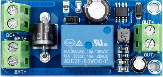
Pin Configuration and Descriptions

Pin Number Name Description
1 V_IN Input voltage from mains power.
2 GND Ground reference for the circuit.
3 V_OUT Output voltage to the load.
4 BAT+ Positive terminal of the internal battery.
5 BAT- Negative terminal of the internal battery.
6 CTRL Control pin for enabling or disabling UPS.
7 COMM Communication pin for data exchange.

Usage Instructions

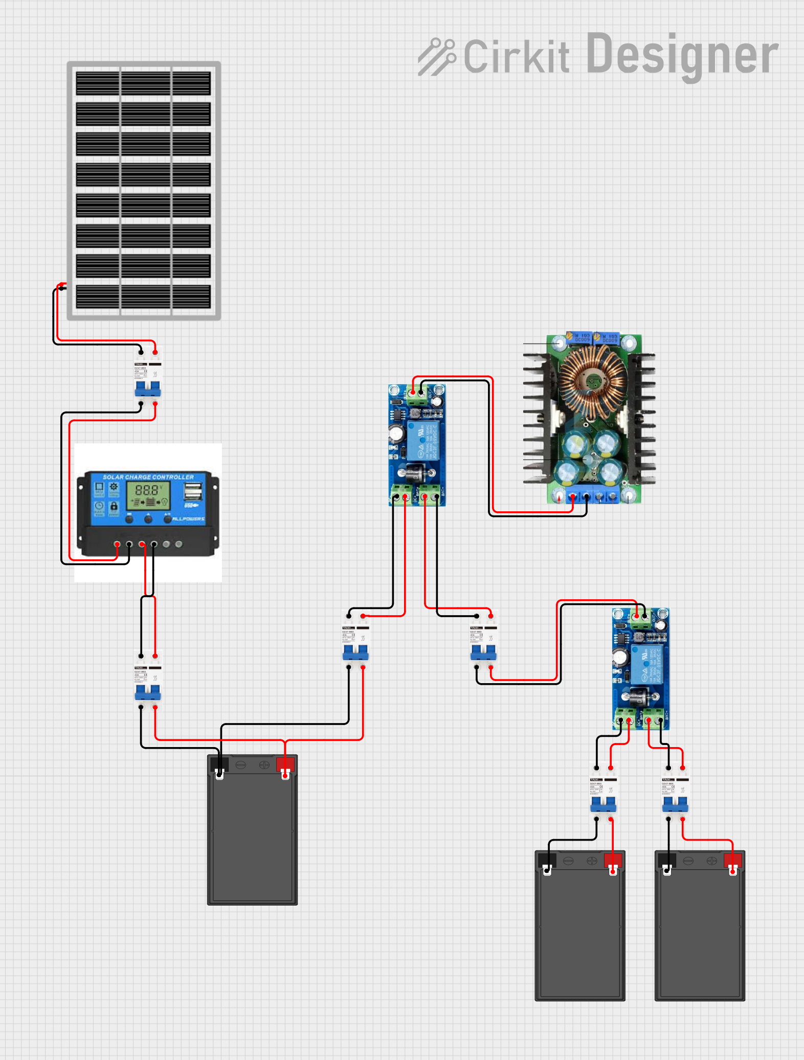
Integration into a Circuit

  1. Power Input: Connect the mains power supply to the V_IN and GND pins, ensuring that the input voltage matches the UPS's specifications.
  2. Load Connection: Attach the load to the V_OUT and GND pins. Ensure that the load does not exceed the UPS's power rating.
  3. Battery Connection: Securely connect the internal battery to the BAT+ and BAT- pins.
  4. Control: Utilize the CTRL pin to enable or disable the UPS module as required by the application.
  5. Communication: Connect the COMM pin to a microcontroller or computer for monitoring and control purposes.

Best Practices

  • Always verify the compatibility of the input voltage and the power rating of the UPS with the connected load.
  • Ensure proper ventilation around the UPS module to prevent overheating.
  • Regularly check and maintain the battery to ensure optimal performance and longevity.
  • Use appropriate surge protection to safeguard the UPS from voltage spikes.

Troubleshooting and FAQs

Common Issues and Solutions

  • UPS not switching to battery: Check the battery connections and charge level. Ensure the transfer switch is functioning correctly.
  • Short battery life: Verify that the battery is not outdated and that it is being charged properly. Consider replacing the battery if it no longer holds a charge.
  • No output voltage: Ensure that the UPS is turned on and that the CTRL pin is correctly configured. Check for any blown fuses or circuit breakers.

FAQs

  • Q: How long will the UPS power the load?

    • A: The backup time depends on the battery capacity and the power consumption of the load. Calculate the expected runtime by dividing the battery capacity (in watt-hours) by the load's power consumption (in watts).
  • Q: Can I replace the battery in the UPS module?

    • A: Yes, most UPS modules allow for battery replacement. Consult the manufacturer's documentation for the correct battery type and replacement procedure.
  • Q: How do I know when the UPS is running on battery power?

    • A: The UPS module typically includes indicators or can communicate its status through the COMM pin to a monitoring system.

Example Code for Arduino UNO

// Example code to monitor UPS status via the COMM pin
int commPin = 2; // Replace with actual COMM pin connected to Arduino
int upsStatus = 0; // Variable to store UPS status

void setup() {
  pinMode(commPin, INPUT);
  Serial.begin(9600);
}

void loop() {
  upsStatus = digitalRead(commPin); // Read the UPS status
  if (upsStatus == HIGH) {
    // UPS is on battery power
    Serial.println("UPS on battery power.");
  } else {
    // UPS is on mains power
    Serial.println("UPS on mains power.");
  }
  delay(1000); // Wait for 1 second before reading again
}

Remember to adjust the commPin variable to match the actual pin used on the Arduino. The example assumes a simple digital signal indicating the power status, which may vary based on the specific UPS module's communication protocol.