How to Use DRIVER TMA.DES.HSS86: Examples, Pinouts, and Specs
Introduction
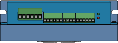
The DRIVER TMA.DES.HSS86 is a high-speed driver specifically designed for transmitting signals in high-frequency applications. It is widely used in telecommunications and data communication systems where reliable and efficient signal transmission is critical. This component is engineered to handle high-speed data rates with minimal signal distortion, making it an essential choice for modern communication systems.
Explore Projects Built with DRIVER TMA.DES.HSS86

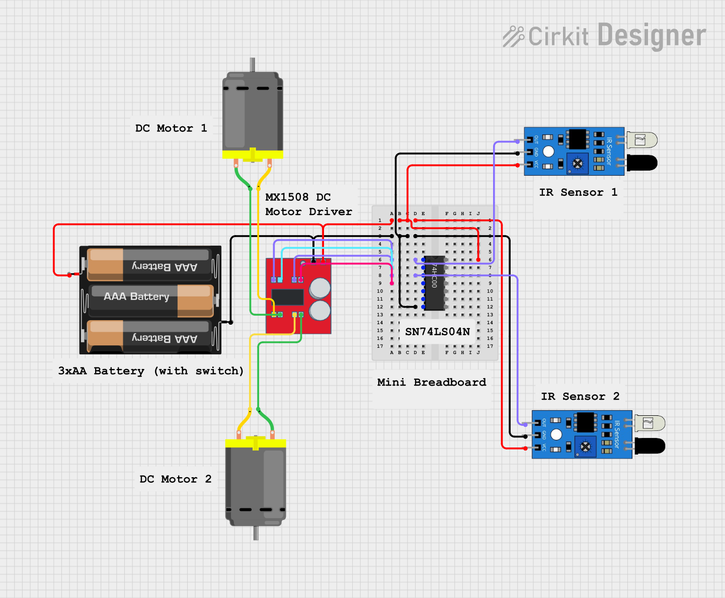


Explore Projects Built with DRIVER TMA.DES.HSS86
Common Applications and Use Cases
- High-frequency signal transmission in telecommunications
- Data communication systems requiring low-latency and high-speed performance
- Signal amplification in RF (Radio Frequency) circuits
- High-speed digital interfaces in networking equipment
Technical Specifications
Key Technical Details
| Parameter | Value |
|---|---|
| Supply Voltage (Vcc) | 3.3V to 5V |
| Operating Frequency | Up to 2 GHz |
| Input Signal Voltage | 0.8V to 3.3V |
| Output Signal Voltage | 0.8V to 3.3V |
| Power Consumption | 150 mW (typical) |
| Operating Temperature | -40°C to +85°C |
| Propagation Delay | < 1 ns |
| Package Type | 8-pin SOIC |
Pin Configuration and Descriptions
| Pin Number | Pin Name | Description |
|---|---|---|
| 1 | Vcc | Power supply input (3.3V to 5V) |
| 2 | IN+ | Non-inverting input signal |
| 3 | IN- | Inverting input signal |
| 4 | GND | Ground connection |
| 5 | OUT+ | Non-inverting output signal |
| 6 | OUT- | Inverting output signal |
| 7 | ENABLE | Enable/disable control for the driver |
| 8 | NC | No connection (leave unconnected or grounded) |
Usage Instructions
How to Use the Component in a Circuit
- Power Supply: Connect the Vcc pin to a stable power source within the range of 3.3V to 5V. Ensure proper decoupling capacitors (e.g., 0.1 µF and 10 µF) are placed close to the Vcc pin to minimize noise.
- Input Signals: Feed the input signals to the IN+ and IN- pins. The driver supports differential input signals for high-speed operation.
- Output Signals: The OUT+ and OUT- pins provide the amplified differential output signals. Connect these to the next stage of your circuit.
- Enable Control: Use the ENABLE pin to control the operation of the driver. Pull the pin high to enable the driver and low to disable it.
- Ground Connection: Connect the GND pin to the ground of your circuit to ensure proper operation.
Important Considerations and Best Practices
- Signal Integrity: Use short and properly terminated traces for high-frequency signals to avoid reflections and signal degradation.
- Thermal Management: Ensure adequate ventilation or heat dissipation if the driver operates at high frequencies for extended periods.
- Bypass Capacitors: Place bypass capacitors close to the Vcc pin to filter out high-frequency noise.
- Differential Signals: For optimal performance, always use differential input and output signals.
Example: Connecting to an Arduino UNO
Although the DRIVER TMA.DES.HSS86 is primarily used in high-frequency applications, it can be interfaced with an Arduino UNO for basic testing or control purposes. Below is an example code snippet to toggle the ENABLE pin using an Arduino:
// Define the pin connected to the ENABLE pin of the driver
const int enablePin = 7;

void setup() {
  // Set the ENABLE pin as an output
  pinMode(enablePin, OUTPUT);

  // Enable the driver by setting the pin HIGH
  digitalWrite(enablePin, HIGH);
}

void loop() {
  // Toggle the ENABLE pin every second
  digitalWrite(enablePin, HIGH);  // Enable the driver
  delay(1000);                    // Wait for 1 second
  digitalWrite(enablePin, LOW);   // Disable the driver
  delay(1000);                    // Wait for 1 second
}
Troubleshooting and FAQs
Common Issues and Solutions
No Output Signal:
- Cause: The ENABLE pin is not set correctly.
- Solution: Ensure the ENABLE pin is pulled high to activate the driver.
Signal Distortion:
- Cause: Improper termination of high-frequency signals.
- Solution: Use proper termination resistors (e.g., 50Ω) at the input and output.
Overheating:
- Cause: Excessive power dissipation or inadequate ventilation.
- Solution: Improve heat dissipation by adding a heatsink or increasing airflow.
Noise on Output Signals:
- Cause: Insufficient decoupling on the power supply.
- Solution: Add bypass capacitors close to the Vcc pin.
FAQs
Q1: Can the DRIVER TMA.DES.HSS86 operate at 1.8V supply voltage?
A1: No, the driver requires a supply voltage between 3.3V and 5V for proper operation.
Q2: Is it necessary to use differential signals for input and output?
A2: While the driver supports single-ended signals, differential signals are recommended for optimal performance in high-frequency applications.
Q3: Can I leave the NC pin floating?
A3: Yes, the NC (No Connection) pin can be left unconnected or tied to ground without affecting the operation.
Q4: What is the maximum data rate supported by the driver?
A4: The DRIVER TMA.DES.HSS86 supports data rates up to 2 GHz, making it suitable for high-speed applications.