How to Use RPi Relay Board: Examples, Pinouts, and Specs
Introduction
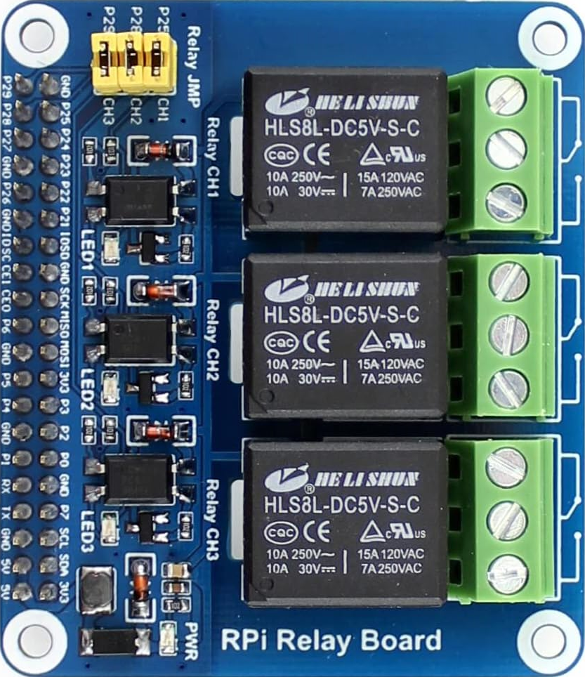
The RPi Relay Board (Manufacturer Part ID: 11638) by Waveshare is a versatile relay module designed specifically for use with the Raspberry Pi. This board allows the Raspberry Pi to control high voltage devices through its GPIO pins, making it ideal for home automation, industrial control, and other applications where high voltage switching is required.
Explore Projects Built with RPi Relay Board
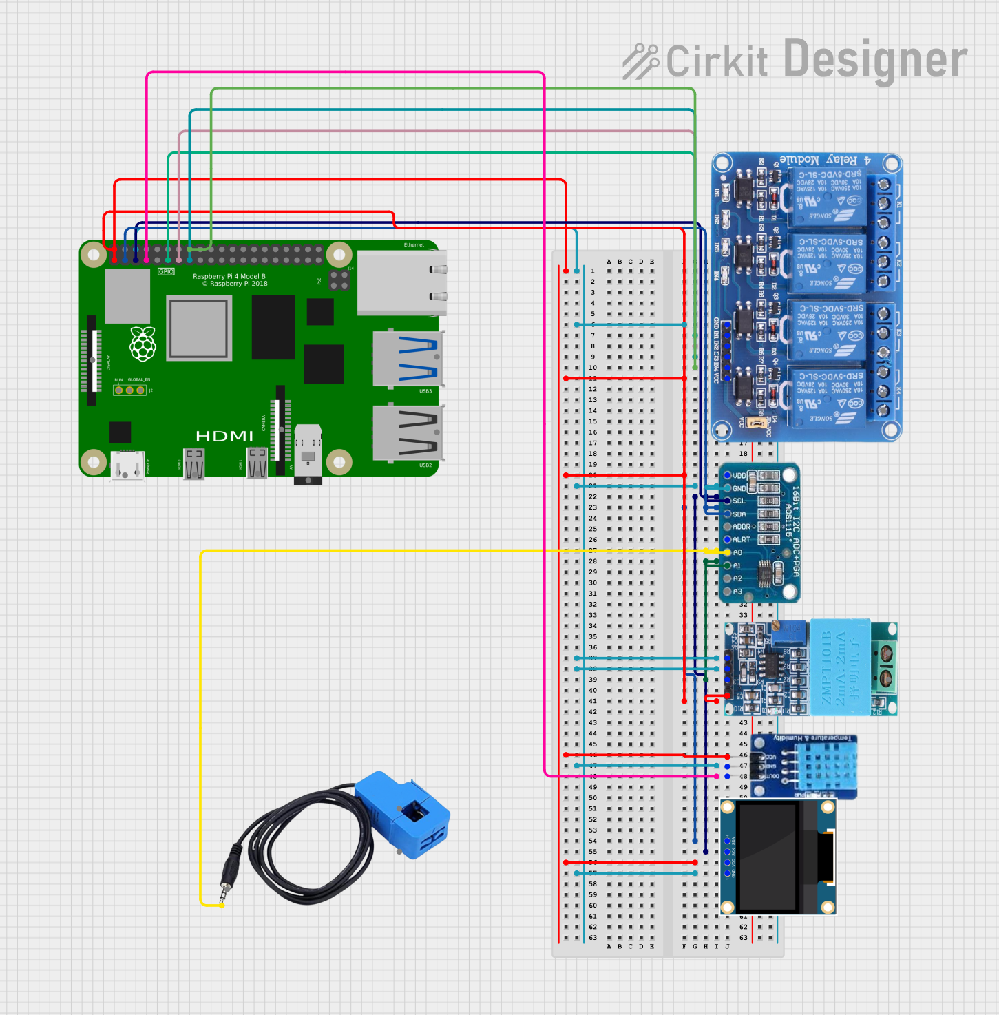
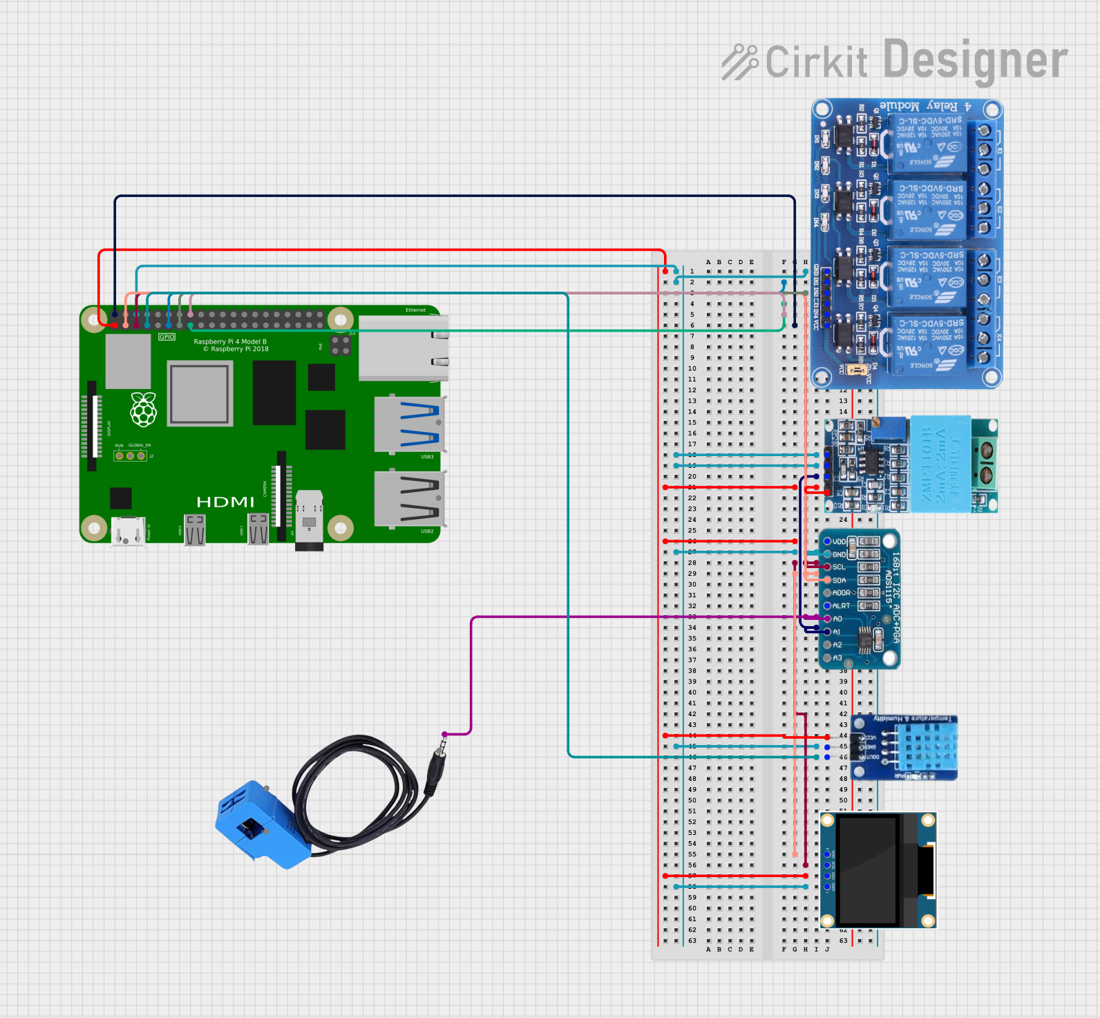
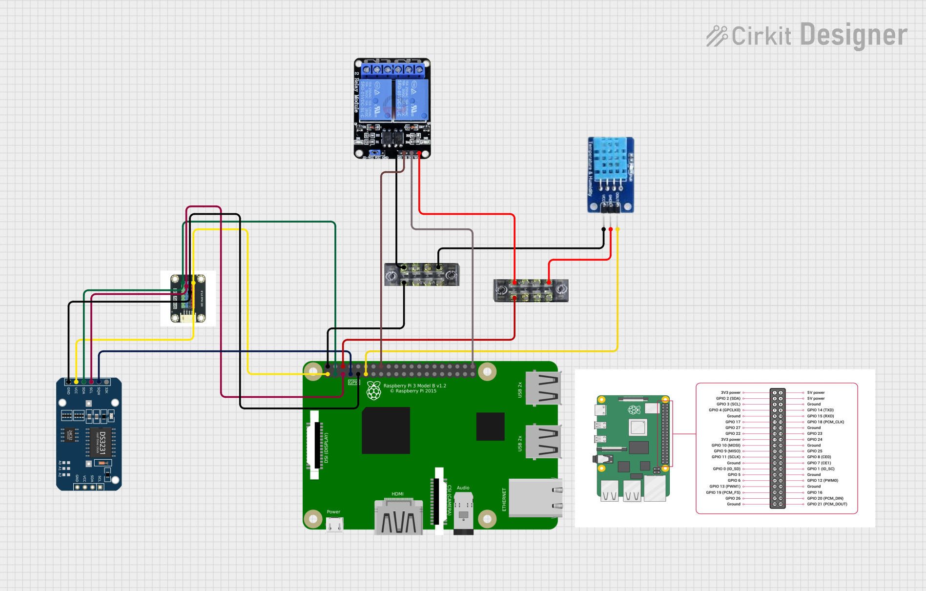
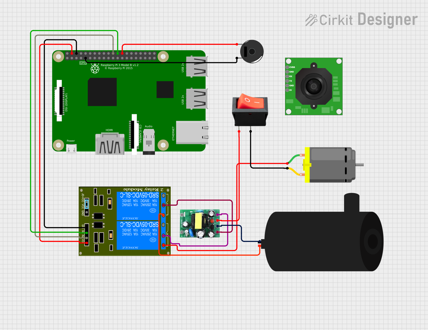
Explore Projects Built with RPi Relay Board
Common Applications and Use Cases
- Home Automation: Control lights, fans, and other household appliances.
- Industrial Control: Manage machinery and equipment in an industrial setting.
- IoT Projects: Integrate with various IoT devices for remote control and monitoring.
- Prototyping: Useful for testing and developing new electronic projects that require high voltage control.
Technical Specifications
Key Technical Details
| Specification | Value |
|---|---|
| Operating Voltage | 5V |
| Relay Channels | 1, 2, 4, or 8 (depending on model) |
| Control Signal | 3.3V (from Raspberry Pi GPIO) |
| Max Switching Voltage | 250V AC / 30V DC |
| Max Switching Current | 10A |
| Dimensions | Varies by model |
| Weight | Varies by model |
Pin Configuration and Descriptions
1-Channel Relay Board
| Pin Name | Description |
|---|---|
| VCC | 5V Power Supply |
| GND | Ground |
| IN | Control Signal from Raspberry Pi GPIO |
2-Channel Relay Board
| Pin Name | Description |
|---|---|
| VCC | 5V Power Supply |
| GND | Ground |
| IN1 | Control Signal for Relay 1 |
| IN2 | Control Signal for Relay 2 |
4-Channel Relay Board
| Pin Name | Description |
|---|---|
| VCC | 5V Power Supply |
| GND | Ground |
| IN1 | Control Signal for Relay 1 |
| IN2 | Control Signal for Relay 2 |
| IN3 | Control Signal for Relay 3 |
| IN4 | Control Signal for Relay 4 |
8-Channel Relay Board
| Pin Name | Description |
|---|---|
| VCC | 5V Power Supply |
| GND | Ground |
| IN1 | Control Signal for Relay 1 |
| IN2 | Control Signal for Relay 2 |
| IN3 | Control Signal for Relay 3 |
| IN4 | Control Signal for Relay 4 |
| IN5 | Control Signal for Relay 5 |
| IN6 | Control Signal for Relay 6 |
| IN7 | Control Signal for Relay 7 |
| IN8 | Control Signal for Relay 8 |
Usage Instructions
How to Use the Component in a Circuit
Power the Relay Board:
- Connect the VCC pin to the 5V pin on the Raspberry Pi.
- Connect the GND pin to the GND pin on the Raspberry Pi.
Connect Control Signals:
- Connect the IN pins to the desired GPIO pins on the Raspberry Pi.
Connect the Load:
- Connect the high voltage device to the relay's Normally Open (NO) and Common (COM) terminals.
Control the Relay:
- Use the Raspberry Pi to send a HIGH signal to the IN pin to activate the relay and a LOW signal to deactivate it.
Important Considerations and Best Practices
- Isolation: Ensure proper isolation between the high voltage and low voltage sides to prevent damage to the Raspberry Pi.
- Current Rating: Do not exceed the maximum current rating of the relay to avoid damage.
- Heat Dissipation: Ensure adequate ventilation to prevent overheating, especially when switching high currents.
- Debouncing: Implement software debouncing to avoid multiple triggering of the relay due to noise.
Example Code for Raspberry Pi
import RPi.GPIO as GPIO
import time
Pin Definitions
relay_pin = 17 # GPIO pin connected to the relay
Pin Setup
GPIO.setmode(GPIO.BCM) # Broadcom pin-numbering scheme GPIO.setup(relay_pin, GPIO.OUT) # Relay pin set as output
Initial state for relay
GPIO.output(relay_pin, GPIO.LOW)
print("Starting relay control. Press CTRL+C to exit.") try: while True: print("Relay ON") GPIO.output(relay_pin, GPIO.HIGH) # Turn relay on time.sleep(2) # Wait for 2 seconds print("Relay OFF") GPIO.output(relay_pin, GPIO.LOW) # Turn relay off time.sleep(2) # Wait for 2 seconds except KeyboardInterrupt: print("Exiting program.") finally: GPIO.cleanup() # Clean up GPIO on exit
Troubleshooting and FAQs
Common Issues Users Might Face
Relay Not Activating:
- Solution: Ensure the control signal voltage is correct (3.3V for Raspberry Pi). Check connections and power supply.
Relay Stuck in ON/OFF Position:
- Solution: Verify the load does not exceed the relay's maximum current rating. Check for mechanical faults in the relay.
Raspberry Pi Reboots When Relay Activates:
- Solution: Ensure proper isolation and use a separate power supply for the relay board if necessary.
Noise and Interference:
- Solution: Implement software debouncing and use capacitors to filter noise.
FAQs
Q1: Can I use the RPi Relay Board with other microcontrollers?
- A1: Yes, the relay board can be used with other microcontrollers that provide a 3.3V or 5V control signal.
Q2: What is the maximum load I can control with the relay?
- A2: The relay can switch up to 250V AC or 30V DC with a maximum current of 10A.
Q3: How do I know if the relay is working?
- A3: The relay typically has an LED indicator that lights up when the relay is activated.
Q4: Can I control multiple relays simultaneously?
- A4: Yes, you can control multiple relays by connecting each relay's IN pin to a different GPIO pin on the Raspberry Pi.
By following this documentation, users can effectively integrate the RPi Relay Board into their projects, ensuring reliable and safe control of high voltage devices.